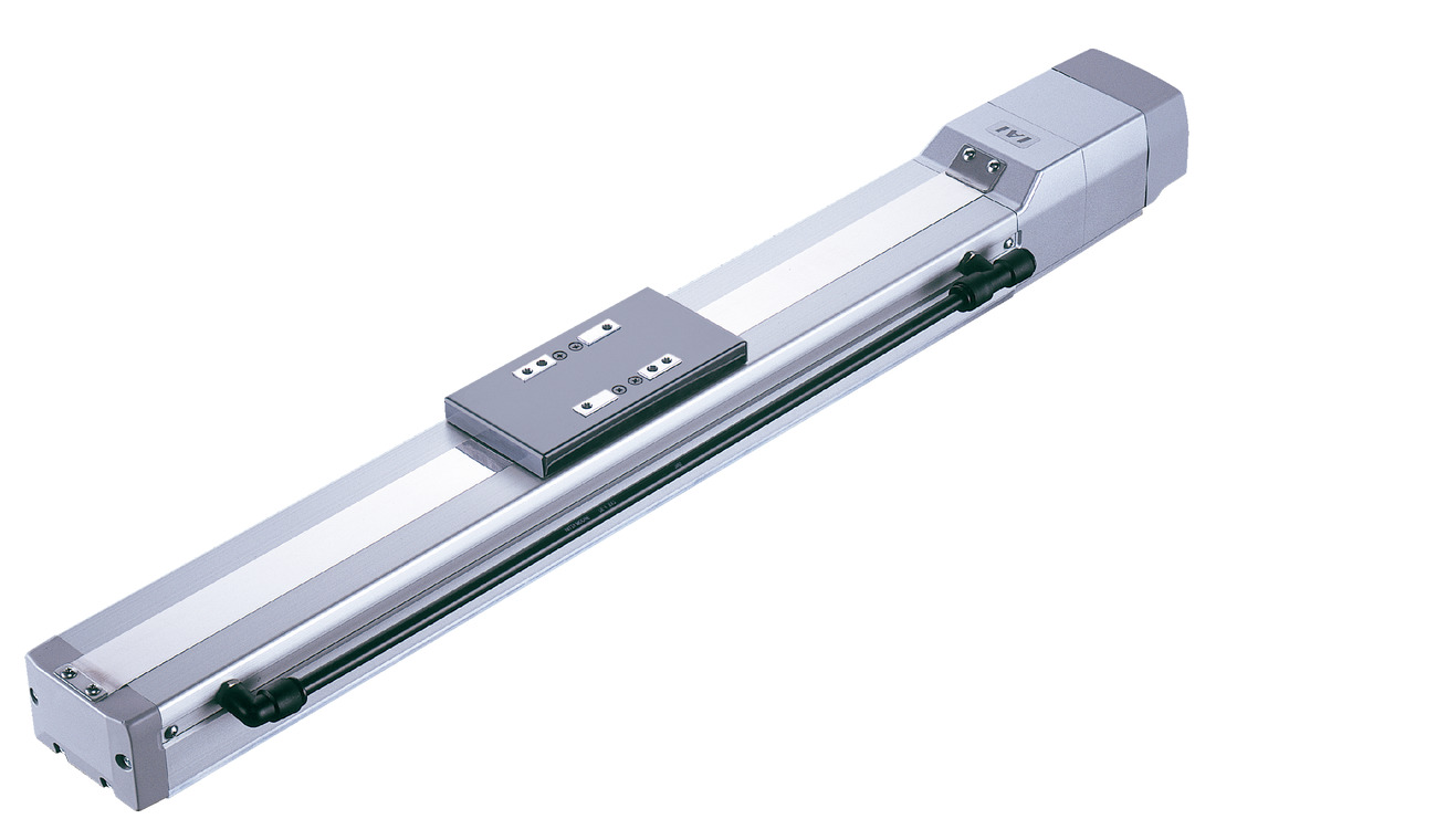
Actuator specification
| Model | Motor output (W) | Lead (mm) | Maximum Load Capacity | Rated thrust (N) | Stroke (mm) | |
|---|---|---|---|---|---|---|
| Horizontal (kg) | Vertical (kg) | |||||
| RCS2CR-SA7C-WA-60-16-①-T2-②-③ | 60 | 16 | 12 | 3 | 63.8 | 50 - 800 (Every 50mm) |
| RCS2CR-SA7C-WA-60-8-①-T2-②-③ | 8 | 25 | 6 | 127.5 | ||
| RCS2CR-SA7C-WA-60-4-①-T2-②-③ | 4 | 40 | 12 | 255.0 | ||
Code explanation ① Stroke ② Cable length ③ Option
| Stroke lead | 50 - 600 (Every 50mm) | ~700 (mm) | ~800 (mm) | Suction amount (Nℓ/min) |
|---|---|---|---|---|
| 16 | 800 | 640 | 480 | 50 |
| 8 | 400 | 320 | 240 | 30 |
| 4 | 200 | 160 | 120 | 10 |
(Measured in mm/s)
Actuator specification
| Heading | Contents |
|---|---|
| Drive system | Ball screw φ12mm, rolled C10 |
| Accuracy of Repeating Positioning. | ±0.02mm |
| Lost motion | 0.1mm or less |
| Base | Material: White alumite treated aluminum |
| Allowable static moment value | Ma:50.4N・m Mb:71.9N・m Mc:138.0N・m |
| Allowable dynamic moment (Note1) | Ma:20.7N・m Mb:29.6N・m Mc:56.7N・m |
| Cleanliness | Class 10 (Fed.Std.209D), equivalent to class 2.5 (ISO 14644-1 standard) |
| Ambient operating temperature and humidity | 0 - 40℃, 85% RH and below (Non-condensing) |
(Note 1) Based on standard rated life of 5,000km. Life time travelling distance differs based on operating condition and attached condition. Refer page 1-180 for the operating life.
Adaptive controller
The actuators introduced in this page are controllable using the controllers shown below. Please select their type based on intended usage.
| Name | Appearance | Max. connectable axis No. | Power source voltage | Control method | Maximum positioning points | ||||||||||||||
|---|---|---|---|---|---|---|---|---|---|---|---|---|---|---|---|---|---|---|---|
| Positioner | Pulse train | Program | Network *Select | ||||||||||||||||
| DV | CC | CIE | PR | CN | ML | ML3 | EC | EP | PRT | SSN | ECM | ||||||||
| MSCON-C | 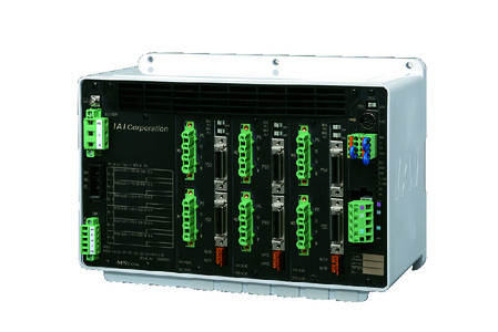 | 6 | Single phase AC 100V/ 200V | - | - | - | ● | ● | - | ● | ● | - | - | ● | ● | - | - | - | 256 |
| SCON-CAL/CGAL | 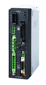 | 1 | ● | - | - | ● | ● | - | ● | ● | ● | - | ● | ● | ● | - | - | 512 (768 for network specification) | |
| SCON-CB/CGB | 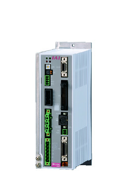 | 1 | ● | ● | - | ● | ● | ● | ● | ● | ● | ● | ● | ● | ● | - | - | 512 (768 for network specification) | |
| SCON-LC/LCG | 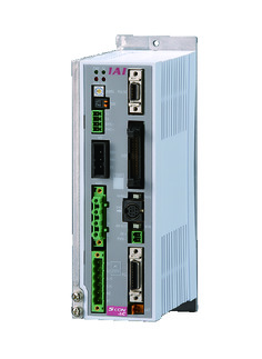 | 1 | - | - | ● | ● | ● | - | ● | ● | ● | - | ● | ● | ● | - | - | 512 (768 for network specification) | |
| SSEL-CS | 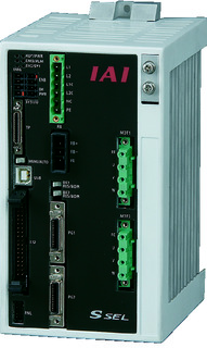 | 2 | ● | - | ● | ● | ● | - | ● | - | - | - | - | ● | - | - | - | 20000 | |
| XSEL-P/Q | 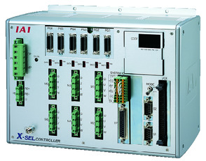 | 6 | Single phase AC200V Three-phase AC200V | - | - | ● | ● | ● | - | ● | - | - | - | - | ● | - | - | - | 20000 |
| XSEL-RA/SA | 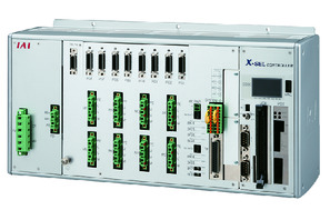 | 8 | - | - | ● | ● | ● | - | ● | - | - | - | ● | ● | - | - | - | 55000 (Vary based on type) | |
(Note) Refer to page 7-17 for network abbreviation symbols such as DV and CC.
Oversea specification
(Note) CE is optional.
Important notes on selection
| (1) Maximum speed drops when the stroke length increase, preventing it from reaching the critical revolution value of the ball screws. Please check the maximum speed of your desired stroke using the actuator specification table below. (2) Load capacity shown assumes an operation in acceleration of 0.3G (0.2G for lead 4). (3) Available duty depends on the operating condition (e.g.load mass, acceleration/deceleration). Refer to page 1-288 for further details. (4) Compatible with cleanliness class 10 only when used horizontally. (5) Refer to page 1-269 for the pressing operation. (6) Precaution is required depending on the attachment orientation. Refer page 1-199 for further details. (7) The approximate overhang load length is 230mm or less in Ma, Mb and Mc directions. (8) Please refer to the diagram on page 1-16 for the allowable moment direction and overhang load length. |
Dimension drawing
ME: Mechanical end
SE: Stroke end
*1 Connect a motor/encoder cable.
Refer to page 1-105 for details of the cable.
*2 When returning to the home position, the slider moves to ME. Please be careful of interference with surrounding objects.
Dimensions in parentheses are reference dimensions.
*3 This is the reference position when calculating the allowable moment.
(Note) In the case of reverse-home specifications, the dimensions on the motor side (distance to the home) and the dimensions on the side opposite the motor will be reversed.
(Note) The total length will increase by 43 mm (56.3 mm if the wiring is taken out at the end) and the mass will increase by 0.6 kg if there is a brake installed.
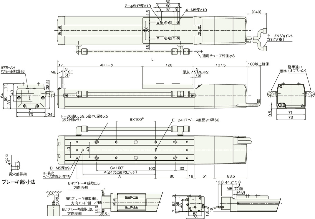
Dimension/Mass by stroke
| Stroke | 50 | 100 | 150 | 200 | 250 | 300 | 350 | 400 | 450 | 500 | 550 | 600 | 650 | 700 | 750 | 800 |
|---|---|---|---|---|---|---|---|---|---|---|---|---|---|---|---|---|
| L | 332.5 | 382.5 | 432.5 | 482.5 | 532.5 | 582.5 | 632.5 | 682.5 | 732.5 | 782.5 | 832.5 | 882.5 | 932.5 | 982.5 | 1032.5 | 1082.5 |
| A | 0 | 100 | 100 | 200 | 200 | 300 | 300 | 400 | 400 | 500 | 500 | 600 | 600 | 700 | 700 | 800 |
| B | 0 | 0 | 0 | 1 | 1 | 2 | 2 | 3 | 3 | 4 | 4 | 5 | 5 | 6 | 6 | 7 |
| C | 0 | 0 | 1 | 1 | 2 | 2 | 3 | 3 | 4 | 4 | 5 | 5 | 6 | 6 | 7 | 7 |
| D | 4 | 6 | 6 | 8 | 8 | 10 | 10 | 12 | 12 | 14 | 14 | 16 | 16 | 18 | 18 | 20 |
| E | 2 | 3 | 3 | 3 | 3 | 3 | 3 | 3 | 3 | 3 | 3 | 3 | 3 | 3 | 3 | 3 |
| F | 4 | 4 | 6 | 6 | 8 | 8 | 10 | 10 | 12 | 12 | 14 | 14 | 16 | 16 | 18 | 18 |
| H | 0 | 1 | 1 | 1 | 1 | 1 | 1 | 1 | 1 | 1 | 1 | 1 | 1 | 1 | 1 | 1 |
| P | 0 | 85 | 85 | 185 | 185 | 285 | 285 | 385 | 385 | 485 | 485 | 585 | 585 | 685 | 685 | 785 |
| Mass (kg) | 2.6 | 2.8 | 3.0 | 3.2 | 3.5 | 3.7 | 3.9 | 4.1 | 4.4 | 4.6 | 4.8 | 5.0 | 5.3 | 5.5 | 5.7 | 5.9 |


