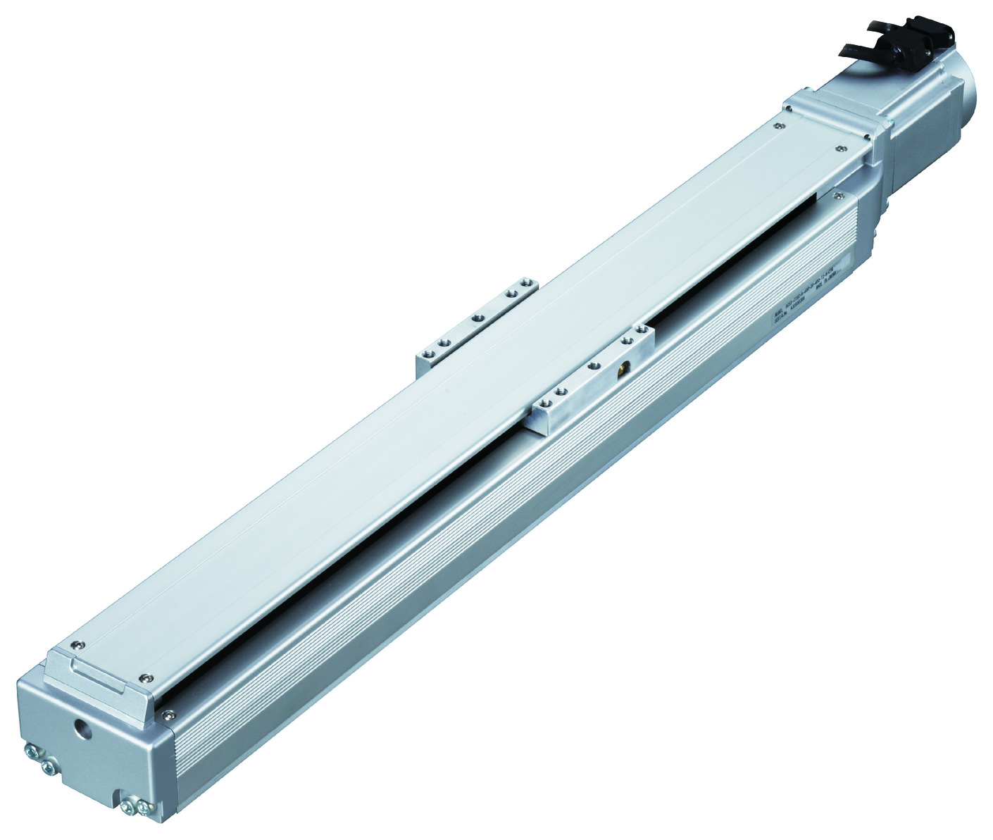
Main specification
| Heading | Contents | ||
|---|---|---|---|
| Lead | Ball screw lead (mm) | 30 | |
| Horizontal | Load capacity | Maximum load capacity (kg) | 5 |
| Speed/ Acceleration/Deceleration | Maximum speed (mm/s) | 2500 | |
| Rated acceleration/deceleration (G) (Note1) | 3.2 (Instantaneous max 4.8G) | ||
| Max. acceleration/deceleration (G) (Note1) | 3.2 (Instantaneous max 4.8G) | ||
| Vertical | Load capacity | Maximum load capacity (kg) | - |
| Speed/ Acceleration/Deceleration | Maximum speed (mm/s) | - | |
| Rated acceleration/deceleration (G) | - | ||
| Maximum acceleration/deceleration (G) | - | ||
| Thrust | Rated thrust (N) | 226 | |
| Stroke | Minimum stroke (mm) | 100 | |
| Maximum stroke (mm) | 500 | ||
| Stroke pitch (mm) | 50 | ||
(Note1) Assumes a S-curve motion type B.
| Heading | Contents |
|---|---|
| Drive system | Ball screw φ16mm, rolled C10 |
| Accuracy of Repeating Positioning. | ±0.02mm |
| Lost motion | 0.05mm and below |
| Base | Material: Aluminum (White anodized) |
| Linear guide | Infinite linear circulation type |
| Allowable static moment value | Ma:144N・m |
| Mb:206N・m | |
| Mc:302N・m | |
| Allowable dynamic moment value (Note2) | Ma:23N・m |
| Mb:33N・m | |
| Mc:48N・m | |
| Ambient operating temperature and humidity | 0 - 40℃, 85% RH Max (Non-condensing) |
| Protection grade | ー |
| Vibration resistant/Shock resistant | 4.9m/s2 100Hz and below |
| Compatible to overseas standards | CE mark, RoHS compliant |
| Motor type | Servo motor |
| Encoder type | Incremental/Absolute |
| Encoder pulse No. | 16384 pulse/rev |
| Mass (kg) | Described on the dimension |
| Delivery | Written in [Reference for delivery] section of the homepage |
(Note2) Assumes a standard rated life of 20,000km and standard load coefficient of 1.35. Life time travelling distance differs based on operating condition and attached condition. Please refer to page 1-360 for life time travelling distance.
Slider type moment direction

Stroke and maximum speed
(Measured in mm/s)
| Stroke lead | 100 - 500 (50mm intervals) |
|---|---|
| 30 | 2500 |
Adaptive controller
The actuators introduced in this page are controllable using the controllers shown below. Please select their type based on intended usage.
| Name | Appearance | Max. connectable axis No. | Power source voltage | Control method | Maximum positioning points | |||||||||||||
|---|---|---|---|---|---|---|---|---|---|---|---|---|---|---|---|---|---|---|
| Positioner | Pulse train | Program | Network ※Select | |||||||||||||||
| DV | CC | PR | CN | ML | ML3 | EC | EP | PRT | SSN | ECM | ||||||||
| SCON-CB/CGB | 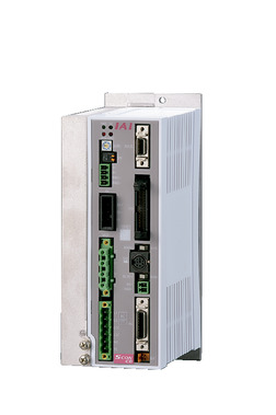 | 1 | Single phase AC200V | ● | ● | - | ● | ● | ● | ● | ● | ● | ● | ● | ● | - | - | 512 (768 for network specification) |
| SCON-LC/LCG | 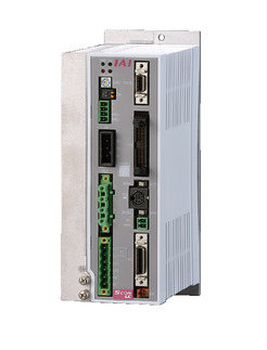 | 1 | - | - | ● | ● | ● | ● | ● | ● | - | ● | ● | ● | - | - | 512 (768 for network specification) | |
| XSEL-P/Q | 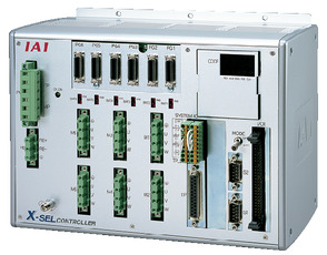 | 6 | Three-phase AC200V | - | - | ● | ● | ● | ● | - | - | - | - | ● | - | - | - | 20000 |
(Note) Please refer to page 6 -13 for abbreviated names of network (e.g. DV, CC).
(Note) Up to 3 axis can be connected if RCS3-CT8C alone was operated with XSEL.
Oversea specification
Important notes on selection
| (1) Only for horizontal orientation. Please take note that this product can't be set in horizontal, sideway or vertical orientation. Precaution is required depending on the attachment orientation. Please refer to page 1-379 for further information. (2) Vibration control and acceleration/deceleration setting for S-curve motion has to be set within the program. (3) A stop time of 0.05 second has to be provided for each cycle for stroke lower than 250mm. Strokes above 250mm are operable in duty of 100%. (4) The standard value for offset load lengths are 445mm and below, towards the direction of Ma, Mb and Mc. Please refer to the diagram on page 1-104 for offset load length. |
Dimension drawing
ST: Stroke
M.E.: Mechanical end
S.E.: Stroke end
(Note) Connect motor encoder cable to the cable joint connector. Please refer to page 1- 295 for the further details about the cable.
(Note) Ensure the slider does not collide with other items, for it will return to M.E. after homing process.
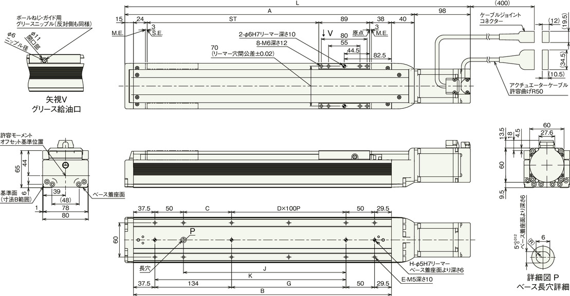
Dimension by stroke length
| Stroke | 100 | 150 | 200 | 250 | 300 | 350 | 400 | 450 | 500 |
|---|---|---|---|---|---|---|---|---|---|
| L | 404 | 454 | 504 | 554 | 604 | 654 | 704 | 754 | 804 |
| A | 306 | 356 | 406 | 456 | 506 | 556 | 606 | 656 | 706 |
| B | 251 | 301 | 351 | 401 | 451 | 501 | 551 | 601 | 651 |
| C | 84 | 34 | 84 | 34 | 84 | 34 | 84 | 34 | 84 |
| D | 0 | 1 | 1 | 2 | 2 | 3 | 3 | 4 | 4 |
| E | 8 | 10 | 10 | 12 | 12 | 14 | 14 | 16 | 16 |
| G | 0 | 50 | 100 | 150 | 200 | 250 | 300 | 350 | 400 |
| H | 3 | 4 | 4 | 4 | 4 | 4 | 4 | 4 | 4 |
| J | 84 | 134 | 184 | 234 | 284 | 334 | 384 | 434 | 484 |
| K | 134 | 184 | 234 | 284 | 334 | 384 | 434 | 484 | 534 |
Mass by stroke length
| Stroke | 100 | 150 | 200 | 250 | 300 | 350 | 400 | 450 | 500 |
|---|---|---|---|---|---|---|---|---|---|
| Mass (kg) | 4.2 | 4.5 | 4.8 | 5.1 | 5.4 | 5.7 | 6.0 | 6.3 | 6.6 |


