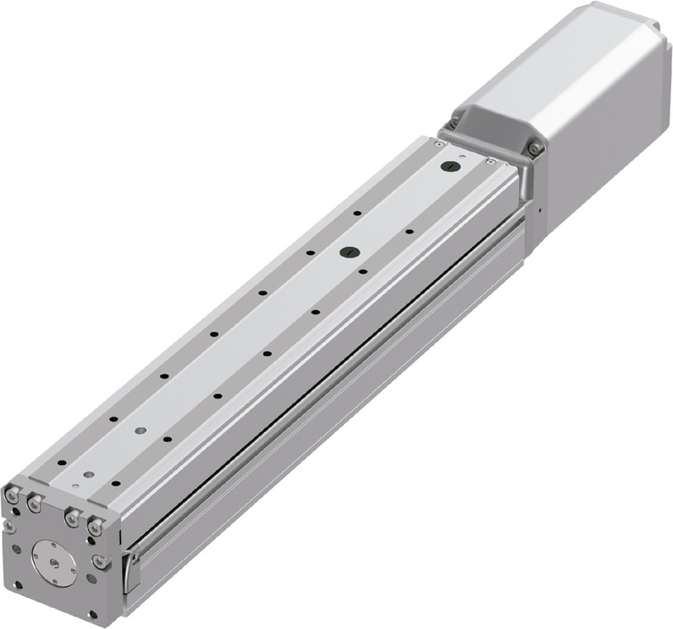
Main specification
| Heading | Contents | ||||
|---|---|---|---|---|---|
| Lead | Ball screw lead (mm) | 16 | 8 | 4 | |
| Horizontal | Load capacity | Maximum load capacity (kg) | 25 | 30 | 30 |
| Speed/ Acceleration/Deceleration | Maximum speed (mm/s) | 960 | 480 | 240 | |
| Rated acceleration/deceleration (G) | 0.5 | 0.5 | 0.7 | ||
| Maximum acceleration/deceleration (G) | 1.2 | 1 | 0.7 | ||
| Vertical | Load capacity | Maximum load capacity (kg) | 8 | 18 | 24 |
| Speed/ Acceleration/Deceleration | Maximum speed (mm/s) | 960 | 480 | 240 | |
| Rated acceleration/deceleration (G) | 1 | 1 | 0.7 | ||
| Maximum acceleration/deceleration (G) | 1.2 | 1 | 0.7 | ||
| Thrust | Rated thrust (N) | 214 | 427 | 855 | |
| Brake | Brake specification | Non-excitation electromagnetic brake | |||
| Brake retention force (kgf) | 8 | 18 | 24 | ||
| Stroke | Minimum stroke (mm) | 40 | 40 | 40 | |
| Maximum stroke (mm) | 390 | 390 | 390 | ||
| Stroke length (mm) (Note1) | 50 | 50 | 50 | ||
(Note1) Stroke between 40 - 90, available in 25 increments.
| Heading | Contents |
|---|---|
| Drive system | Ball screw φ12mm, rolled C10 |
| Accuracy of Repeating Positioning. | ±0.01mm |
| Lost motion | 0.1mm and below |
| Base | Base: Aluminum, with white alumite treatment |
| Linear guide | Infinite linear circulation type |
| Allowable static moment value | Ma:620N・m |
| Mb:620N・m | |
| Mc:458N・m | |
| Allowable dynamic moment (Note2) | Ma:196N・m |
| Mb:196N・m | |
| Mc:145N・m | |
| Ambient operating temperature and humidity | 0 - 40℃, Max 85% RH and below (No condensation shall occur) |
| Protection grade | ー |
| Vibration resistant/Shock resistant | 4.9m/s2 100Hz and below |
| Compatible to overseas standards | CE mark, RoHS compliant |
| Motor type | AC servo motor |
| Encoder type | Battery-less absolute |
| Encoder pulse No. | 16384 pulse/rev |
| Delivery | Written in [Reference for delivery] section of the homepage |
(Note2) Assumes a standard rated life of 5,000km. Life time travelling distance differs based on operating condition and attached condition. Please refer to page 1-342 for life time travelling distance.
Moment direction for table types

Load capacity by acceleration
The base unit for load capacity is kilogram (kg). Empty column refers to inoperable motion.
| Orientation | Horizontal | Vertical | ||||||||
|---|---|---|---|---|---|---|---|---|---|---|
| Lead (mm) | Acceleration (G) | |||||||||
| 0.3 | 0.5 | 0.7 | 1.0 | 1.2 | 0.3 | 0.5 | 0.7 | 1.0 | 1.2 | |
| 16 | 25 | 25 | 20 | 20 | 15 | 8 | 8 | 8 | 8 | 6 |
| 8 | 30 | 30 | 25 | 25 | 18 | 18 | 18 | 18 | ||
| 4 | 30 | 30 | 30 | 24 | 24 | 24 | ||||
Stroke and maximum speed
(Measured in mm/s)
| Stroke lead | 40 - 290 (mm) | 340 (mm) | 390 (mm) |
|---|---|---|---|
| 16 | 960 | 730 | 600 |
| 8 | 480 | 365 | 300 |
| 4 | 240 | 180 | 150 |
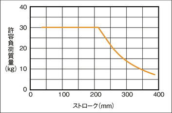
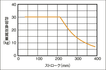
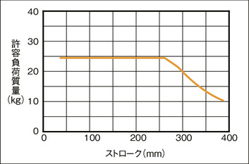
Allowable dynamic moment by stroke
(Note) Condition required upon calculating allowable load mass: Load mass which assures 5000km lifetime traveling distance for a guide, considering the moments resulting from acceleration and deceleration (acceleration of 0.5G, and speed of 500m/s).
Horizontal Sideway mounting
Horizontal Upright mounting
Vertical
Adaptive controller
The actuators introduced in this page are controllable using the controllers shown below. Please select their type based on intended usage.
| Name | Appearance | Max. connectable axis No. | Power source voltage | Control method | Maximum positioning points | ||||||||||||||
|---|---|---|---|---|---|---|---|---|---|---|---|---|---|---|---|---|---|---|---|
| Positioner | Pulse train | Program | Network ※Select | ||||||||||||||||
| DV | CC | CIE | PR | CN | ML | ML3 | EC | EP | PRT | SSN | ECM | ||||||||
| MSCON-C | 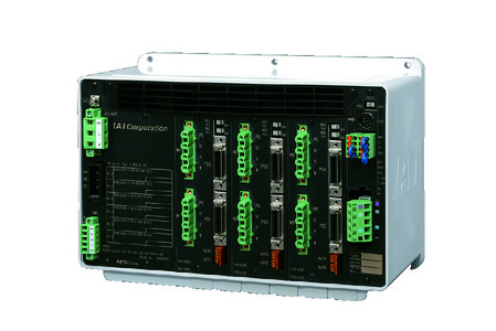 | 6 | Single phase AC 100V/200V | - | - | - | ● | ● | - | ● | ● | - | - | ● | ● | - | - | - | 256 |
| SCON-CAL/CGAL |  | 1 | ● | - | - | ● | ● | - | ● | ● | ● | - | ● | ● | ● | - | - | 512 (768 for network specification) | |
| SCON-CB/CGB |  | 1 | ● | ● | - | ● | ● | ● | ● | ● | ● | ● | ● | ● | ● | - | - | 512 (768 for network specification) | |
| SCON-LC/LCG |  | 1 | - | - | ● | ● | ● | - | ● | ● | ● | - | ● | ● | ● | - | - | 512 (768 for network specification) | |
| SSEL-CS |  | 2 | ● | - | ● | ● | ● | - | ● | - | - | - | - | ● | - | - | - | 20000 | |
| XSEL-P/Q | 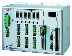 | 6 | Single phase AC200V Three-phase AC200V | - | - | ● | ● | ● | - | ● | - | - | - | - | ● | - | - | - | 20000 |
| XSEL-RA/SA | 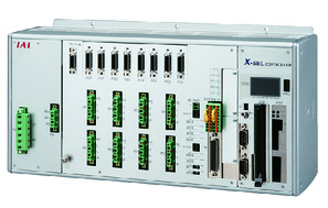 | 8 | - | - | ● | ● | ● | - | ● | - | - | - | ● | ● | - | - | - | 55000 (Vary based on type) | |
(Note) Please refer page 7-15 for network abbreviations such as DV and CC.
Oversea specification
Important notes on selection
| (1) Maximum speed drops when the stroke length increase, preventing it from reaching the critical revolution value of the ball screws. Use the "Stroke and Max.speed" to check the maximum speed at the stroke you desire. (2) Load capacity drops when its speed increases. Please refer to "Load capacity by speed table" for further details. (3) Available duty depends on the operating condition (e.g.load mass, acceleration/deceleration). Refer page 1-452 for further information. (4) Due to mechanical limit, allowable load mass drops in longer strokes. Refer "Allowable dynamic moment by stroke length" for further information. (5) Safety measures may be required depending on the attachment orientation. Please refer to page 1-361 for further details. (6) Overhang load length has to be within the range of allowable dynamic moment. Refer user's manual for displacement volume of the table. (7) Allowable static moment refers to the linear guide allowance straight above the guide block on table top (Standard allowable moment offset position). Refer page 1-341 for further information. |
Dimension drawing
ST: Stroke
M.E.: Mechanical end
S.E.: Stroke end
(Note) Please take extra care during origination to prevent the table from colliding against any interfering object, for it moves to M.E. during the process.
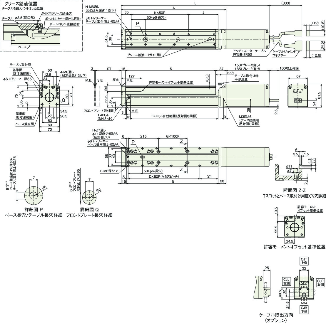
Dimension by stroke length
| Stroke | 40 | 65 | 90 | 140 | 190 | 240 | 290 | 340 | 390 | |
|---|---|---|---|---|---|---|---|---|---|---|
| L | Brake present | 466 | 491 | 516 | 566 | 616 | 666 | 716 | 766 | 816 |
| Brake absent | 501 | 526 | 551 | 601 | 651 | 701 | 751 | 801 | 851 | |
| A | 316 | 341 | 366 | 416 | 466 | 516 | 566 | 616 | 666 | |
| B | 269 | 294 | 319 | 369 | 419 | 469 | 519 | 569 | 619 | |
| C | 64 | 39 | 64 | 64 | 64 | 64 | 64 | 64 | 64 | |
| D | 4 | 5 | 5 | 6 | 7 | 8 | 9 | 10 | 11 | |
| E | 10 | 12 | 12 | 14 | 16 | 18 | 20 | 22 | 24 | |
| G | 0 | 0 | 0 | 1 | 1 | 2 | 2 | 3 | 3 | |
| H | 4 | 4 | 4 | 6 | 6 | 8 | 8 | 10 | 10 | |
| J | 103 | 78 | 103 | 103 | 103 | 103 | 103 | 103 | 103 | |
| K | 3 | 4 | 4 | 5 | 6 | 7 | 8 | 9 | 10 | |
| N | 8 | 10 | 10 | 12 | 14 | 16 | 18 | 20 | 22 | |
| S | 264 | 289 | 314 | 364 | 414 | 464 | 514 | 564 | 614 | |
Mass by stroke length
| Stroke | 40 | 65 | 90 | 140 | 190 | 240 | 290 | 340 | 390 | |
|---|---|---|---|---|---|---|---|---|---|---|
| Mass (kg) | Brake present | 5.3 | 5.5 | 5.7 | 6.2 | 6.6 | 7.1 | 7.5 | 8.0 | 8.4 |
| Brake absent | 5.8 | 6.0 | 6.2 | 6.7 | 7.1 | 7.6 | 8.0 | 8.5 | 8.9 | |


