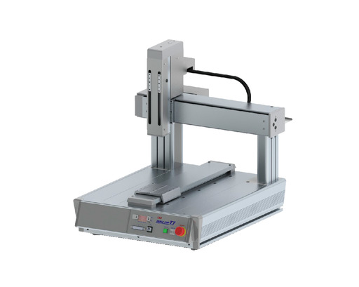
Product feature


Model specification
| Model | Axis Configuration | Encoder type | Motor type | Lead (mm) | Stroke (mm) | Speed (mm/s) | Load Capacity (kg) |
|---|---|---|---|---|---|---|---|
| TTA-A3(G)-WA-30-30②-③B④-⑤-⑥-⑦-⑧-⑨-⑩ | X axis | Battery-less absolute | Pulse motor | Equivalent to 24 | 300 | 1~800 | 20 |
| Y axis | Equivalent to 24 | 300 | 1~800 | - | |||
| Z axis | 12 | 100/150 | 1~400 | 6 |
Symbol description ① ② XY-axis option ③ Z-axis stroke ④ Z-axis option ⑤ Standard I/O slot ⑥ ⑦ Expansion I/O slot ⑧ I/O cable length ⑨ Power cable specification ⑩ Option
Actuator specification
| Heading | Contents |
|---|---|
| Motor type | Pulse motor |
| Drive system | Ball screw (X, Y-axes: φ12 mm Z-axis: φ10 mm Rolled, C10) X, Y-axes: Speeds up by 1.5:1 using a timing belt |
| Accuracy of Repeating Positioning. | ±0.01mm |
| Lost motion | 0.05mm and below |
| Dynamic allowable moment | X-axis:Ma:18.8Nm Mb:18.8Nm Mc:37.8Nm Y-axis:Ma:14.9Nm Mb:14.9Nm Mc:44.3Nm Z-axis:Ma:11.5Nm Mb:11.5Nm Mc:24.3Nm |
| Ambient temperature/humidity | 0 - 40℃, RH 85% and below (no condensation) |
| Table part loading weight (Note 2) | 30kg |
| Body weight | 34.3kg |
(Note 2) The table part is the upper surface of the main body excluding the slider part. It is not the payload of the X axis.
Oversea specification


(Note) CE is compatible only with safety category compliant specifications.
Important notes on selection
| (1) The maximum acceleration/deceleration differs depending on the load capacity. (Refer to page 4-593) The maximum speed cannot be reached with the maximum load setting of the pulse motor. If increase speed, the load capacity will drop. (Refer to page 4-595 onwards) (2) The repeated positioning accuracy is for when the machine temperature is constant. It will not guarantee the absolute accuracy. (3) The value of the dynamic allowable moment is the value of each axis. When the standard rated life is 5,000 km and the standard load factor is 1.5. (For the dynamic allowable moment, refer to page 4-597) (4) Enter "E" if the expansion I/O slots 1 and 2 in the model item are unused. |
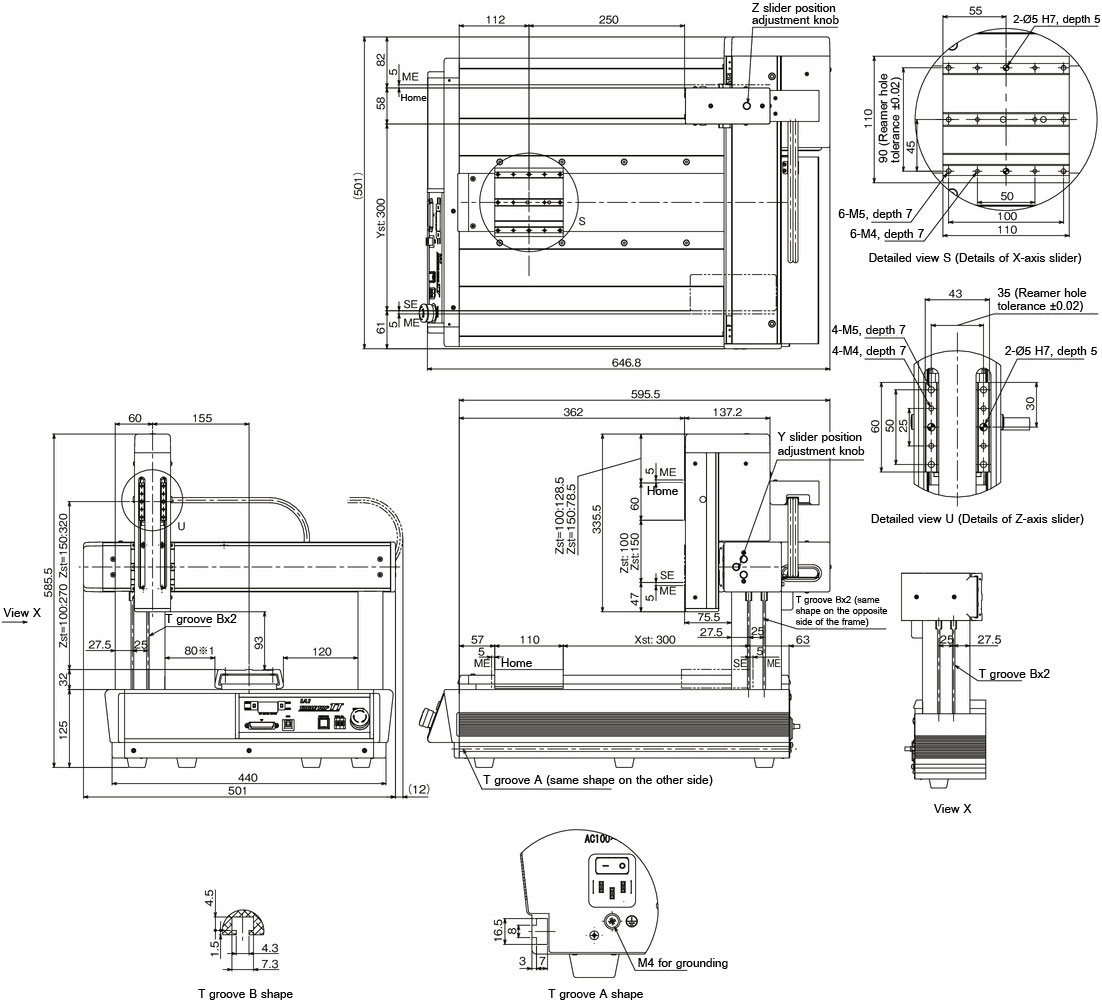
Dimension drawing

ME: Mechanical end
SE: Stroke end
*1 When placing a work on the X slider, make sure that there is a margin of 2 mm or more for the main frame.
(Note) During home return, the slider moves to the mechanical end. Pay attention to prevent contact between the slider and the surrounding.