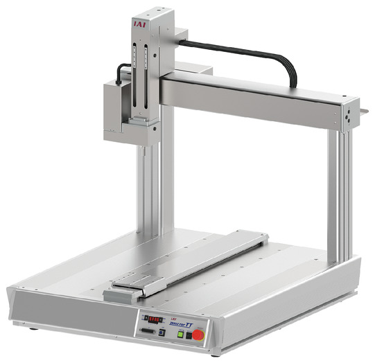
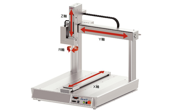
Direction in which each axis moves
Main specification
| Heading | Contents | ||||
|---|---|---|---|---|---|
| A4SL(G) | A4SH(G) | A4(G) | |||
| Lead | Ball screw lead (mm) | X axis | 8 | 16 | Equivalent to 24 |
| Y axis | 8 | 16 | Equivalent to 24 | ||
| Z axis | Equivalent to 2.14 | Equivalent to 5 | 12 | ||
| R axis | ー | ||||
| Maximum load capacity (kg) | X axis | 30 | 15 | 20 | |
| Y axis | ー | ー | ー | ||
| Z axis | 15 | 7 | 6 | ||
| R axis | |||||
| Speed/ Acceleration/Deceleration | Maximum speed | X-axis (mm/s) | 600 | 1200 | 800 |
| Y-axis (mm/s) | 600 | 1200 | 800 | ||
| Z-axis (mm/s) | 170 | 400 | 400 | ||
| R-axis (degrees/s) | 1500 | 1500 | 1000 | ||
| Max. acceleration/deceleration (G) | X axis | 0.5 | 0.7 | 0.4 | |
| Y axis | 0.5 | 0.7 | 0.4 | ||
| Z axis | 0.3 | 0.5 | 0.2 | ||
| R axis | 1.5 | 1.5 | 1.1 | ||
| Push Motion (Note 3) | Max. thrust during push motion | Z-axis (N) | 140 | 60 | 103 |
| R-axis (N・m) | 0.53 | 0.53 | 0.85 | ||
| Brake (equipped as standard on Z-axis) | Brake specification | Non-excitation electromagnetic brake | |||
| Brake retention force (kgf) | 15 | 7 | 6 | ||
| Stroke | X-axis (mm) | 500 | |||
| Y-axis (mm) | 500 | ||||
| Z-axis (mm) | 100/150 | ||||
| R-axis (degrees) | ±180/±360 | ||||
(Note 3) Push motion is only available on the Z-axis and R-axis.
(Note) The rough guideline for the R-axis overhang load length is a radius of 100 mm or less.
| Heading | Contents | |||
|---|---|---|---|---|
| A4SL(G) | A4SH(G) | A4(G) | ||
| Drive system | X axis | Ball screw φ12mm, rolled C5 equivalent | Ball screw φ12mm, rolled C10 equivalent 1.5: 1 speed increase with timing belt | |
| Y axis | ||||
| Z axis | Ball screw φ10mm, rolled C5 equivalent | Ball screw φ10mm, rolled C10 | ||
| 1:1.4 speed reduction with timing belt | 1:1.2 speed reduction with timing belt | |||
| Accuracy of Repeating Positioning. | X axis | ±0.005mm | ±0.01mm | |
| Y axis | ||||
| Z axis | ||||
| R axis | ±0.008 degrees | ±0.01 degrees | ||
| Lost motion | X axis | 0.025mm or less | 0.04mm and below | 0.05mm and below |
| Y axis | ||||
| Z axis | 0.02mm and below | |||
| R axis | 0.06 degrees or less | 0.06 degrees or less | ||
| Allowable static moment value | X axis | Ma:62.7N・m Mb:62.7N・m Mc:126.5N・m | ||
| Z axis | Ma:35.0N・m Mb:35.0N・m Mc:74.0N・m | |||
| R axis | ||||
| Dynamic allowable moment | X axis | Ma:18.8N・m Mb:18.8N・m Mc:37.8N・m | ||
| Z axis | Ma:11.5N・m Mb:11.5N・m Mc:24.3N・m | |||
| R axis | ||||
| Max. load moment of inertia | R axis | 0.01kg・m2 | ||
| Ambient operating temperature and humidity | 0 - 40℃, RH 85% and below (no condensation) | |||
| Protection grade | ー | |||
| Vibration resistant/Shock resistant | 4.9m/s2 | |||
| Compatible to overseas standards | CE mark (safety category type only), RoHS Directive | |||
| Motor type | AC servo motor | Pulse motor | ||
| Encoder type | Battery-less absolute | |||
| Encoder pulse No. | 16384 pulse/rev | 8192 pulse/rev | ||
| Delivery | Written in [Reference for delivery] section of the homepage | |||
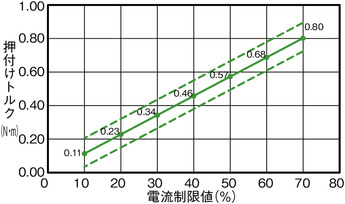
Correlation diagram of pressing force and current limiting value
■ Servo motor equipped model A4SL (G)/A4SH (G)
Z axis
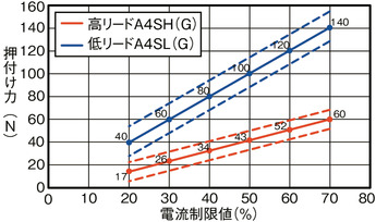
(Note) There is a variation (dotted line) in the pushing force, which is ±10% of the maximum force.
R axis
Please contact us if you wish to have the push control function on the rotation axis (R-axis).
(Note) There is a variation (dotted line) in the pushing force, which is ±10% of the maximum force.
■ Pulse motor equipped model A4 (G)
Z axis
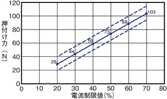
(Note) There is a variation (dotted line) in the pushing force, which is ±10% of the maximum force.
R axis
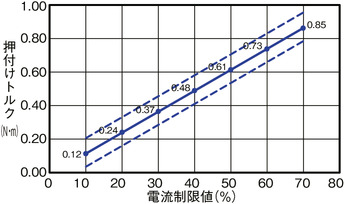
Please contact us if you wish to have the push control function on the rotation axis (R-axis).
(Note) There is a variation (dotted line) in the pushing force, which is ±10% of the maximum force.
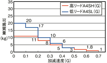
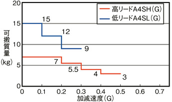
Correlation Diagram of Acceleration and Load Capacity
■ Servo motor equipped model A4SL (G)/A4SH (G)
X axis
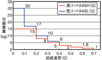
Y axis
Z axis
Correlation diagram between payload and speed
Due to the characteristics of pulse motors, as the speed increases, the payload capacity decreases.
Please use the table below to confirm that your desired speed and payload are met.
X axis
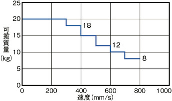
Please refer to the table below for the set acceleration/deceleration.
Y axis
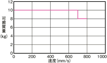
The acceleration/deceleration should be set to 0.4G or less.
Z axis
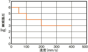
The acceleration/deceleration should be set to 0.2G or less.
Payload mass and acceleration/deceleration
| Load capacity | Acceleration/Deceleration |
|---|---|
| 20kg | 0.2G and below |
| 18kg | 0.2G and below |
| 15kg | 0.3G and below |
| 12kg | 0.3G and below |
| 10kg | 0.4G and below |
| 8kg | 0.4G and below |
Correlation Diagram of Acceleration and Load Capacity
■ Servo motor equipped model A4SL (G)/A4SH (G)
ZR-axis
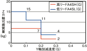
The payload of the ZR axis changes depending on the acceleration/deceleration of the Y axis.
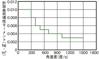
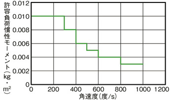
Correlation diagram of R-axis allowable load moment of inertia and angular velocity
■ Servo motor equipped model A4SL (G)/A4SH (G)
■ Pulse motor equipped model A4 (G)
| Allowable load moment of inertia | Angular velocity | Angular acceleration/deceleration |
|---|---|---|
| 0.010kg・m2 | 300 degrees/s | 0.05G |
| 0.008kg・m2 | 400 degrees/s | 0.1G |
| 0.006kg・m2 | 500 degrees/s | 0.2G |
| 0.005kg・m2 | 700 degrees/s | 0.5G |
| 0.004kg・m2 | 1000 degrees/s | 1G |
| 0.003kg・m2 | 1500 degrees/s | 1.5G |
| Allowable load moment of inertia | Angular velocity | Angular acceleration/deceleration |
|---|---|---|
| 0.010kg・m2 | 100 degrees/s | 0.1G |
| 0.010kg・m2 | 200 degrees/s | 0.1G |
| 0.010kg・m2 | 300 degrees/s | 0.1G |
| 0.008kg・m2 | 400 degrees/s | 0.18G |
| 0.006kg・m2 | 500 degrees/s | 0.28G |
| 0.005kg・m2 | 600 degrees/s | 0.4G |
| 0.004kg・m2 | 700 degrees/s | 0.55G |
| 0.004kg・m2 | 800 degrees/s | 0.7G |
| 0.003kg・m2 | 900 degrees/s | 0.9G |
| 0.003kg・m2 | 1000 degrees/s | 1.1G |
Oversea specification
(Note) CE is compatible only with safety category compliant specifications.
Important notes on selection
| (1) The maximum acceleration/deceleration differs depending on the load capacity. (Refer to "Correlation diagram of acceleration/deceleration and payload capacity") The maximum speed cannot be achieved with the maximum payload setting when using a pulse motor. If increase speed, the load capacity will drop. Please note that the rotation axis may not reach the maximum speed depending on the load inertia moment value. (Refer to "Correlation diagram of payload and speed" and "Correlation diagram of R-axis allowable load moment of inertia and angular velocity") (2) Repetitive positioning accuracy is effective only when the body temperature is constant. It will not guarantee the absolute accuracy. (3) The value of the dynamic allowable moment is the value of each axis. Assumes a standard rated life of 5,000km and a standard load factor of 1.5. (Please refer to page 5-692 for dynamic allowable moments.) (4) In the expansion I/O slots 1 and 2 columns of the model item, enter "E" if they are unused. |
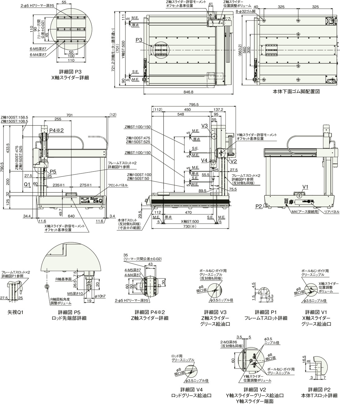
Dimension drawing
ST: Stroke
M.E.: Mechanical end
S.E.: Stroke end
*1 When placing a workpiece on the X slider, make sure that there is a margin of 2 mm or more relative to the main body frame.
*2 If you select the option with cover (model: CO), a cover will be attached to the front of the Z-axis and the slider will be hidden.
(Note) Please be careful while returning to the home position, for there is a chance of collision while having the slider returning to the M.E. position.
Mass
| Heading | Mass | |
|---|---|---|
| AC servo motor | Pulse motor | |
| Body weight | 49.3kg | 48.3kg |
| Table part loading weight (Note 4) | 50kg | |
(Note 4) The table section refers to the top surface of the main body excluding the slider section. It is not the payload of the X axis.


