Product information of RCON
Features of RCON
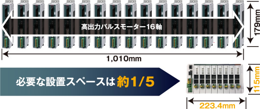
Feature 1 Installation space required are 1/5 of conventional models.
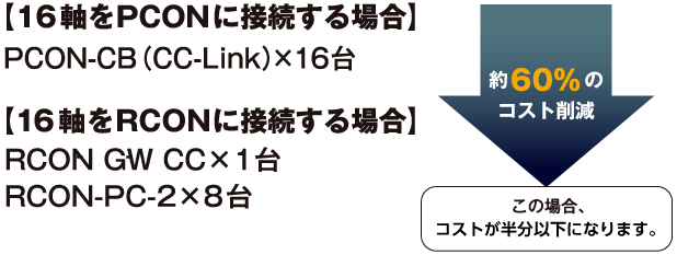
Feature 2 Cuts down cost
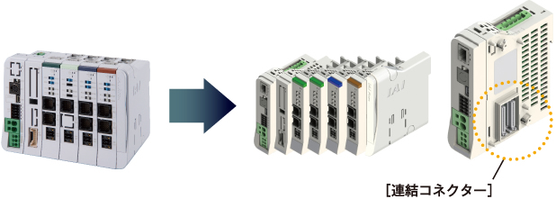
Feature 3 Unit-linked type with high expansion capability.
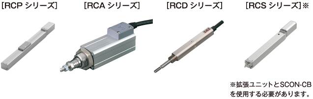
Feature 4 Compatible to all 24V actuators.
-
Model list
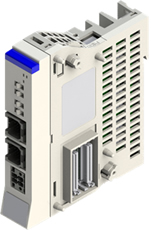
■Gateway unitModel RCON-GW/GWG Appearance 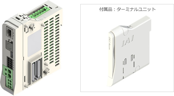
Interface 


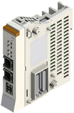
CCLink specification CCLink IE specification DeviceNet specification EtherNet/IP specification EtherCAT specification PROFIBUS-DP specification PROFINET-I/O specification CC CIE DV EP EC PR PRT ■Unit driverModel RCON-PC-1
RCON-PC-2RCON-PCF-1 RCON-AC-1
RCON-AC-2RCON-DC-1
RCON-DC-2Appearance 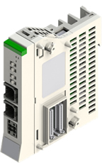
Model entry
■Gateway unit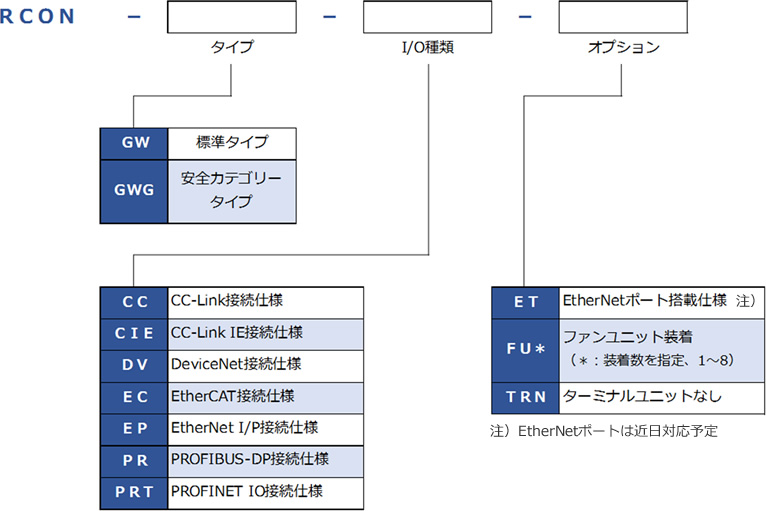 ■Unit driver
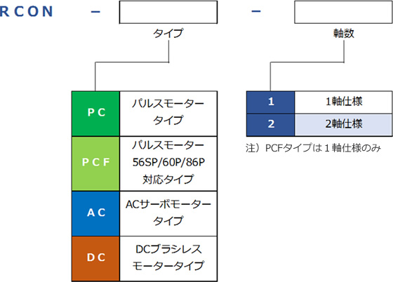
Unit composition
RCON units can be ordered individually, and be combined based on intended usage.
Up to 16 units of actuators can be connected.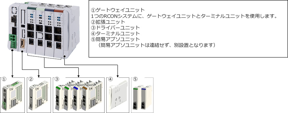
-
Specification
■General specificationItem Specification No. of controlled axis 1 - 16 axis Power source voltage DC24V±10% Control power capacity
(per unit)Gateway unit
(including the terminal unit)0.8A (EtherNet option:Absent) Driver unit
(Common for all types)Brake: Absent 0.2A Brake: Present (1-axis specification) 0.4A Brake: Present (2-axis specification) 0.6A Expansion unit 0.1A Simple absolute unit (Common for all types) 0.2A Motor power capacity
(per actuator axis)Actuator/Driver unit Rated current Maximum current While energy
saving modePulse motor
/RCON-PC20P/28P PowerCon: Absent 0.8A - - 28P/35P/42P/56P PowerCon: Absent 1.9A - - PowerCon: Present 2.3A - 3.9A Pulse motor 56P/56SP/60P/86P PowerCon: Absent 5.7A - - AC Servo motor
/RCON-ACRCA 5W Standard/High acceleration/deceleration 1.0A - 3.3A 10W Standard/High acceleration/deceleration/
Energy saving1.3A 2.5A 4.4A 20W 1.3A 2.5A 4.4A 20W (20S) 1.7A 3.4A 5.1A 30W 1.3A 2.2A 4.0A RCL 2W Standard/High acceleration/deceleration/
Energy saving0.8A - 4.6A 5W 1.0A - 6.4A 10W 1.3A - 6.4A DC Brushless motor
/RCON-DC3W Standard 0.7A - 1.5A 10W 1.3A - 6.4A Inrush current (appx. 5ms) RCON-PC 8.3A RCON-PCF 10.0A RCON-AC 10.0A RCON-DC 10.0A Heating value
(per unit)RCON-PC PowerCon: Absent 5.0W PowerCon: Present 8.0W RCON-PCF PowerCon: Absent 19.2W RCON-AC Standard/High acceleration/deceleration 4.5W RCON-DC Standard 3.0W SIO
InterfaceTeaching port Communicating method RS485 Communication speed 9.6/19.2/38.4/57.6/115.2/230.4 kbps USB port Communicating method USB Communication speed 12Mbps Preventive/Predictive maintenance feature Lowered electrolytic capacitor capacity, lowered fan rotation speed Protection grade IP20 Shock prevention mechanism Class Ⅲ Laws and regulation CE Marking UL certified
(Acquisition planned)■Environment specificationItem Specification Ambient Temperature 0 - 55 (with temperature derating),
and 0 - 40 for simple absolute unitOperating humidity 85% RH and below, without dew condensation Storage Ambient Temperature -20 - 70℃, and 0 - 40℃ for simple absolute unit Operating atmosphere In clean atmosphere, free of dust and corrosive gas Altitude 1,000m Vibration resistance Frequency 10 - 57Hz / Amplitude: 0.075mm, Frequency 57 - 150Hz / Acceleration 9.8m/s2
Each direction of XYZ Sweeping time: 10 minute Sweeping count: 10 timesShock resistance Drop height 800mm, test by dropping 1 on corner, 3 on edges, 6 on sides Over-voltage category Ⅰ Contamination level Ⅱ Caution
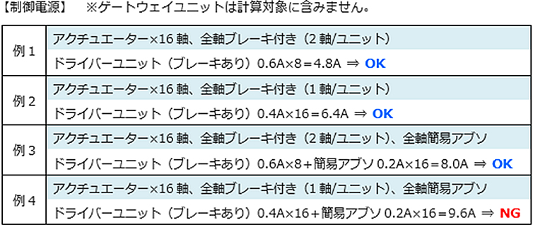
■Power capacity calculationPower capacity can be separated to control power capacity and motor power capacity.
Required power capacity may be calculated by summing the "Total control power capacity of the unit" and "Total motor power capacity of the connected actuators"
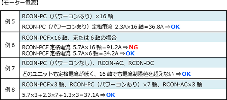
The rated current of DC24V power supply has to be above the total rated current of the motor power capacity, and at the same time, the peak current has to be above the total maximum current of the motor power capacity.
If connecting multiple axis, the rated current and maximum current will not flow on the same time, unless all actuators move at the same time, and due to this, the actual required power capacity will be a little complicated.
We hereby prepared a "Calculator software", which calculates the required power capacity whenever the actuator operating condition and action pattern is set. Please refer to "Calculator manual (MJ0381)" for further details.■Total current of connected unitCalculates the control power for each units and motor power based on RCON system configuration.
Please confirm that the result does not exceed the selection calculation current limit stated below.
The calculation does not include the gateway unit current for the value are too small to be included.Heading Current limit for selection calculation Control power (CP) 9.0A and below Motor power (MP) 37.5A and below Actual calculation will be as shown below.
Caution
●If the action pattern is set in the way that it accelerate or decelerate all axis at the same time, with action duty of 100%, the motor current has to be calculated with maximum current value.
●If you may need a detailed calculation, please use the "Calculator software". Calculates the required power capacity whenever the actuator operating condition and action pattern is set.
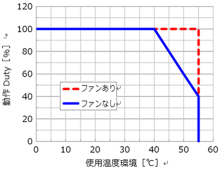
Please refer to "Calculator manual (MJ0381)" for further details.●Operating temperatureThe operating temperature of gateway unit and driver unit are between 0 - 55℃.
Temperature derating will be applied based on absence or presence of fan unit.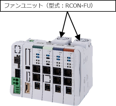
Without a fan unit, the unit may operate without derating between 0 - 40℃, but the action duty has to be cut down by 20% for every 5℃ between 40 - 55℃. With a fan unit, there will be no derating applied up to 55℃.
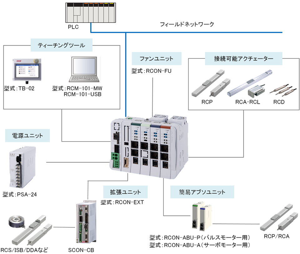
Example of system configuration
Peripheral unit
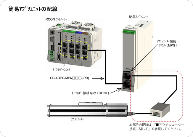
●Simple absolute unit
Model RCON-ABU-①
Model ①Entry Usage RCON-ABU-P P RCP series RCON-ABU-A A RCA series Specification
Item Specification Mass Appx. 270g (183g for battery) Ambient Temperature 0~40℃ Used battery AB-7 (Cylindrical sealed nickel hydride storage battery) Average battery life span Appx. 3 years (Differs largely based on operating condition) Accessories Connection cable (CB-ADPC-MPA005) Wiring method
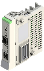
 ■Expansion unit
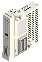
Model RCON-EXT
Specification
Item Specification Mass Appx. 99g Accessories Terminal connector (RCON-EXT-TR) ※If you order a SCON controller with a RCON connection specification, 0.2m (CB-RE-CTL002) SCON connector cable will be sent along as an expansion unit.
If you require a connector cable longer than 0.2m, please order them separately.Wiring method
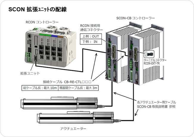
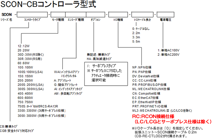
RCON connected SCON model
 ■Power supply unit
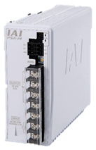
Model PSA-24①
Model ①Entry Cooling fan Power capacity PSA-24 No entry None 204W PSA-24L L Present 300W Specification
●General specificationHeading Specification Conditions PSA-24 PSA-24L Supply voltage range AC100V~AC230V±10% Supply current AC100V 2.5A and below 3.9A and below Continuous rated output 204W AC200V 1.4A and below 1.9A and below Continuous rated output 204W Supply frequency range 50/60Hz±5% Power capacity AC100V 250VA 390VA Continuous rated output 204W AC200V 280VA 380VA Continuous rated output 204W Inrush current *1 AC100V 27.4A (typ) During cold start (40℃) AC200V 54.8A (typ) Tolerance to instantaneous power failure 50Hz 20ms 60Hz 16ms Shock prevention mechanism Class Ⅰ Efficiency AC100V 86% and above Continuous rated output 204W AC200V 90% and above Output voltage range *2 24V±10% Continuous rated output 8.5A (204W) 13.8A (330W) Peak output 17A (408W) Protective feature Overcurrent protection, overheating protection, overload protection, over-voltage protection,
low input voltage protection, fan rotation detectionProtection grade Not applicable Heating value AC100V 28.6W 204W at continuous rated value AC200V 20.4W 204W at continuous rated value Cooling method Natural air cooling Forced air cooling
by fan unitInsulation breakdown voltage AC input - DC output Leakage current 10mA AC3000V 1 minute AC input - FG Leakage current 10mA AC2000V 1 minute DC output - FG Leakage current 25mA AC500V 1 minute Insulation resistance AC input - DC output DC500V 50MΩ and above AC input - FG DC500V 50MΩ and above DC output - FG DC500V 50MΩ and above Leakage current *3 AC100V 0.40mA typ AC200V 0.75mA typ Safety standard UL61010, EN61010-1
KC(EMC), EN55011*1 Pulse width for inrush current will be 5ms and below. Inrush current will be added on for each number added if run on parallel operation.
■Environmental specification
Please select carefully, understanding and choosing based on characteristics so that the inrush current may not trigger the circuit breaker.
*2 The relevant power supply has a characteristic to modify output voltage based on load, to enable parallel operation.
Hence, the relevant power supply is specially for IAI controller. Please refer to the user's manual for further details on output voltage characteristic based on load.
*3 Leakage current regulation for power supply alone.Heading Specification Conditions Ambient Temperature 0℃~+55℃
(with derating)Operating humidity 85%RH and below No condensation dew Storage Ambient Temperature -20℃~+70℃ Atmosphere Dust corrosive gas free clean atmosphere Altitude 2,000m Vibration resistance Frequency 10 - 57Hz / Amplitude: 0.075mm Frequency 57 - 150Hz / Acceleration/Deceleration 9.8m/s2 Each direction of XYZ Sweeping time: 10 minute Sweeping count: 10 times Packaging shock resistance test Drop height 800mm / 1 corner 3 edges 6 sides Over-voltage category Ⅱ Contamination level 2 Installation site Indoor -
External dimension diagram
■Gateway unit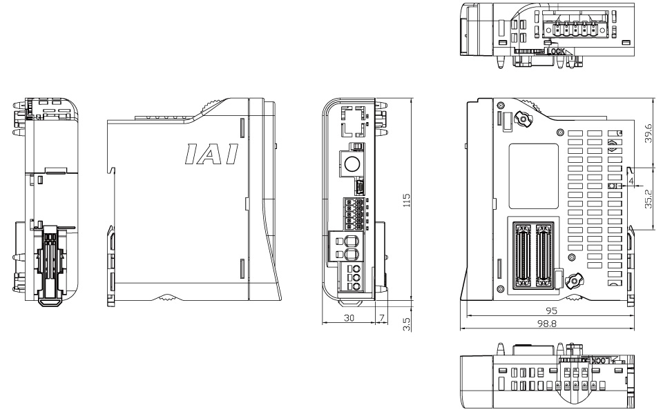 ■Terminal unit
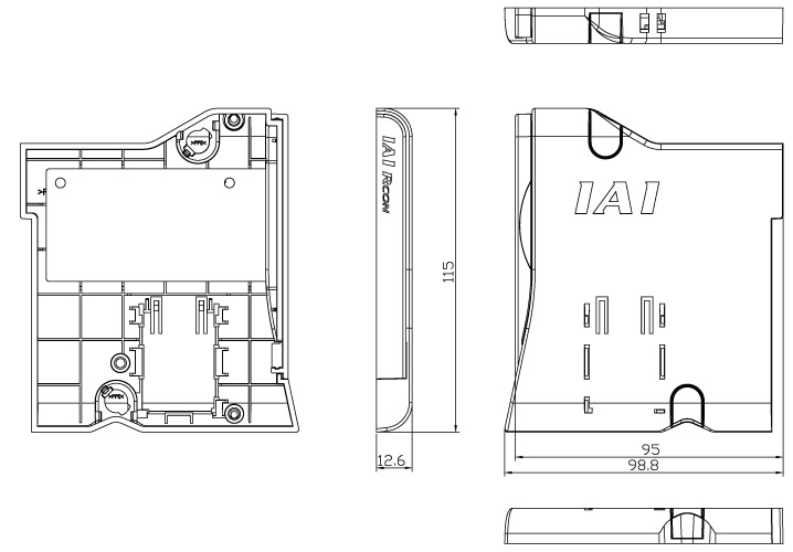 ■Unit driver
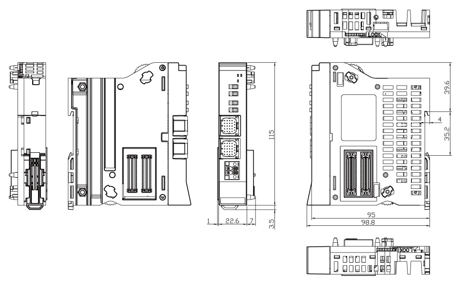 ■SCON expansion unit
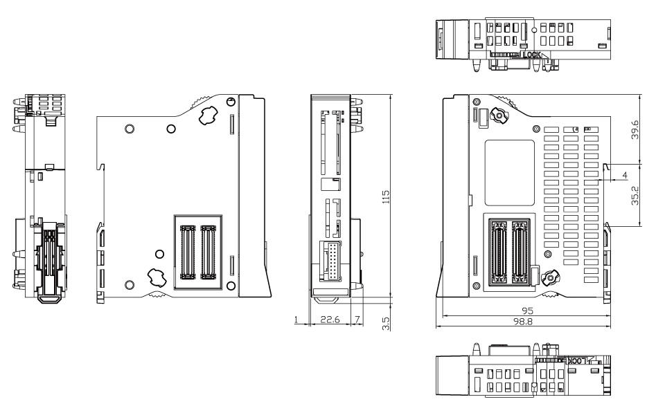 ●Simple absolute unit
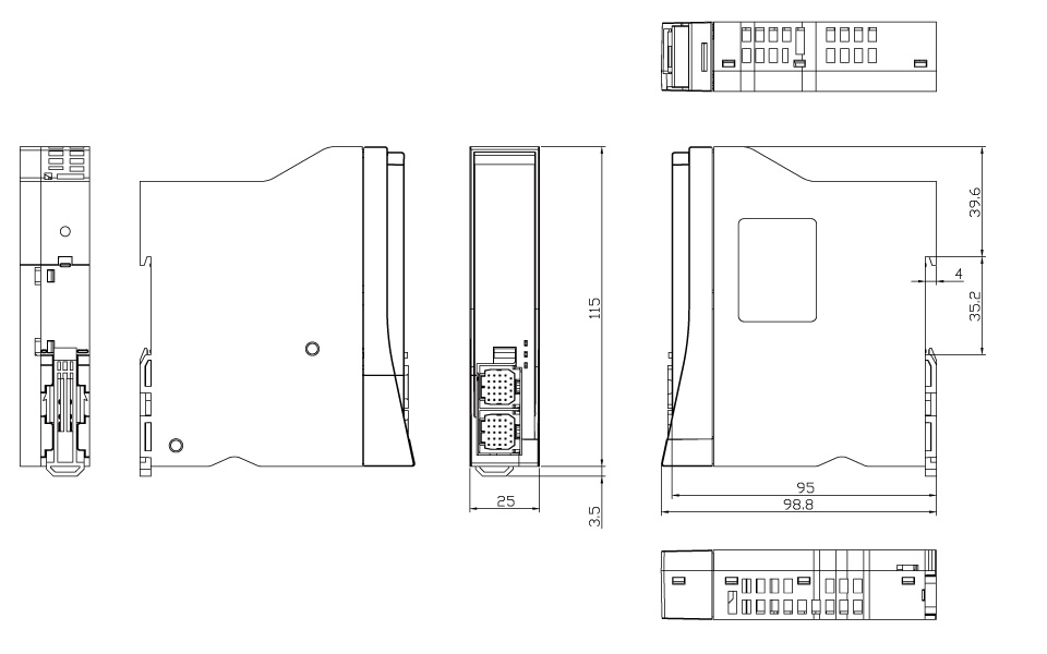 ■Fan unit
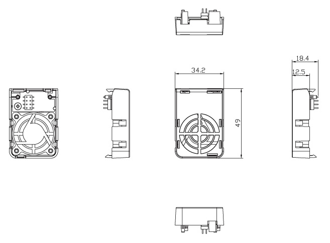 ■Power supply unitWithout fan
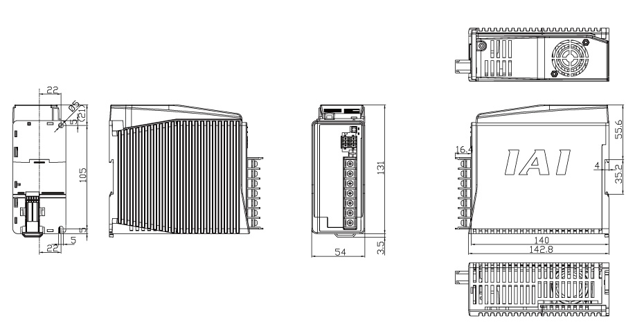
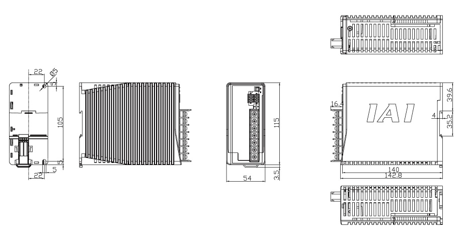 With fan
Installation method
■RCON systemRCON installation condition is as shown below. Condition is fixed to of below regardless of absence or presence of fan.
Simple absolute unit has the same condition as of the below.Heading Specification Install Installing direction Vertical installation (Exhaust directed upwards) Installation method DIN rail mounting Installation requirement Refer diagram Ground D type installation 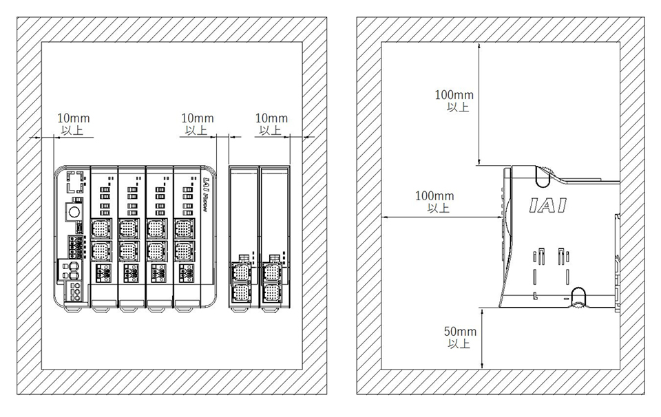 ■Power supply unit
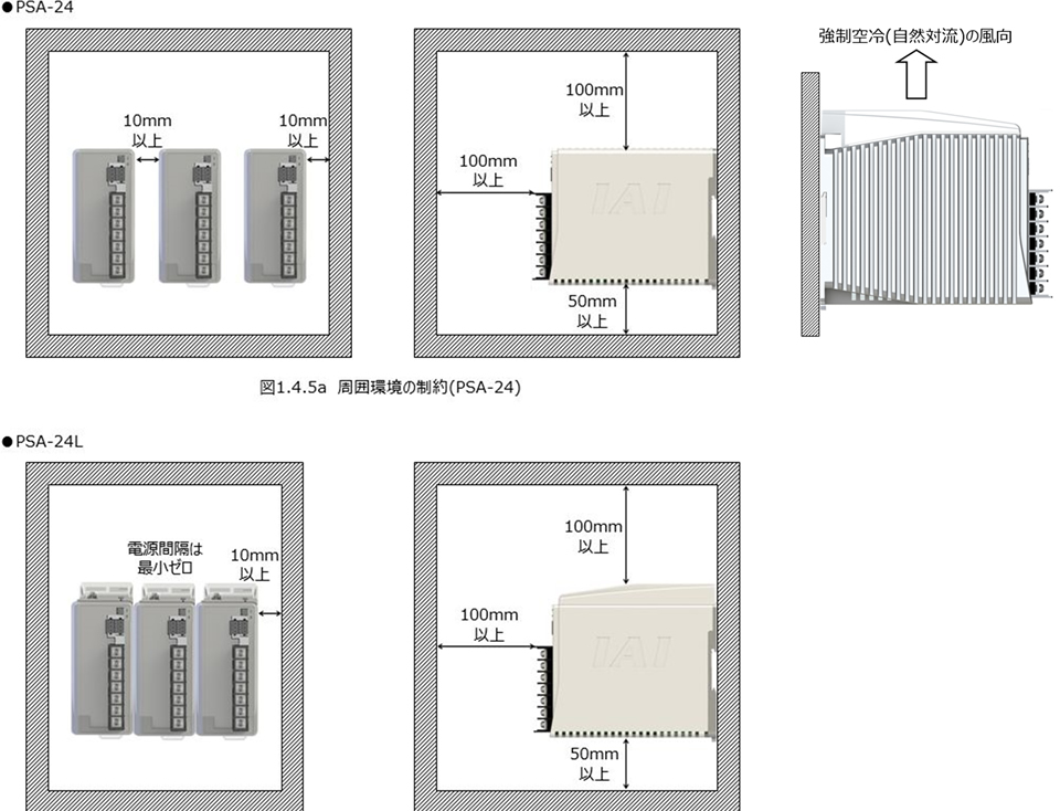
Power supply unit installation condition is as shown below.
Heading Specification Install Installing direction ※1 Horizontal installation Installation method Screw mounting or DIN rail mounting Installation requirement Refer diagram Ground Single ground by type D ground *1 Installing direction has to be as shown in diagram below.
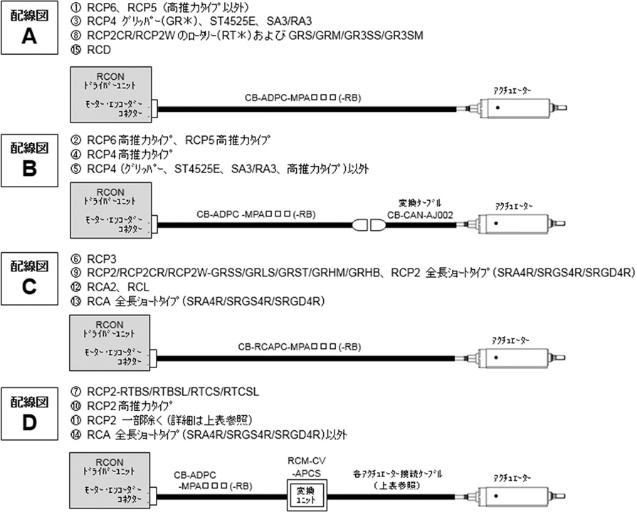
About actuator connection
Connection between RCON driver unit and actuator varies based on actuator types.
Topology, cable models required and required items are noted below.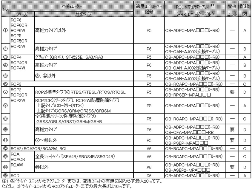
-
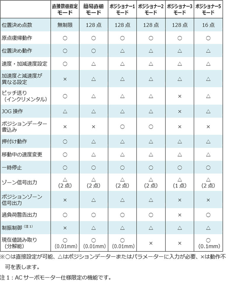
Field network controlled operation mode

Feature list based on operation modes
-
Order method
RCON units has to be ordered individually, and be combined by customer.
Hence, after purchase modification and addition are easy.
Please take note that the connectable axis are limited to 16, and there are also limits on total current for connected units.<Example of an order> Please take note that the order in case you may need to operate 3 actuators as shown below, through CC-Link will be as shown below.
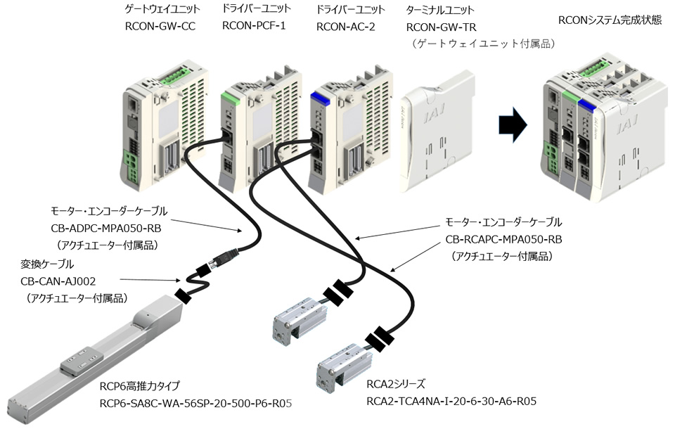 ■Essential items to be ordered
Product name Model Quantity Actuator RCP6
high thrust typeRCP6-SA8C-WA-56SP-20-500-P5-R05 1 RCON driver unit RCON-PCF-1 1 Actuator RCA2
seriesRCA2-TCA4NA-I-20-6-30-A6-R05 2 RCON driver unit RCON-AC-2 1 RCON gateway unit RCON-GW-CC 1 ■Items to be ordered based on needsProduct name Model Quantity PC Software RCM-101-USB 1 Teaching Box TB-02 1 ■Items to be downloaded from the official homepageProduct name Model Quantity Gateway parameter configuration tool - 1 Packaging format