Main specification
| Heading | Contents | |||||
|---|---|---|---|---|---|---|
| Lead | Ball screw lead (mm) | 20 | 12 | 6 | 3 | |
| Horizontal | Load capacity | Max. load capacity (kg) (Power saving disabled) | 6 | 25 | 40 | 60 |
| Max. load capacity (kg) (Power saving enabled) | 6 | 25 | 40 | 40 | ||
| Speed/ Acceleration/Deceleration | Maximum speed (mm/s) | 800 | 700 | 450 | 225 | |
| Minimum speed (mm/s) | 25 | 15 | 8 | 4 | ||
| Rated acceleration/deceleration (G) | 0.3 | 0.3 | 0.3 | 0.3 | ||
| Maximum acceleration/deceleration (G) | 1 | 1 | 1 | 1 | ||
| Vertical | Load capacity | Max. load capacity (kg) (Power saving disabled) | 1.5 | 4 | 10 | 12.5 |
| Max. load capacity (kg) (Power saving enabled) | 1 | 4 | 10 | 12.5 | ||
| Speed/ Acceleration/Deceleration | Maximum speed (mm/s) | 800 | 700 | 450 | 225 | |
| Minimum speed (mm/s) | 25 | 15 | 8 | 4 | ||
| Rated acceleration/deceleration (G) | 0.3 | 0.3 | 0.3 | 0.3 | ||
| Maximum acceleration/deceleration (G) | 0.5 | 0.5 | 0.5 | 0.5 | ||
| Pressing motion | Max. pressing thrust (N) | 67 | 112 | 224 | 449 | |
| Max. pressing speed (mm/s) | 20 | 20 | 20 | 20 | ||
| Brake | Brake specification | Non-excitation electromagnetic brake | ||||
| Brake retention force (kgf) | 1.5 | 4 | 10 | 12.5 | ||
| Stroke | Minimum stroke (mm) | 65 | 65 | 65 | 65 | |
| Maximum stroke (mm) | 315 | 315 | 315 | 315 | ||
| Stroke pitch (mm) | 50 | 50 | 50 | 50 | ||
| Heading | Contents | |
|---|---|---|
| Drive system | Ball screw φ10mm, rolled C10 | |
| Accuracy of Repeating Positioning. | ±0.05mm | |
| Lost motion | - (Can't be shown as this is a 2-point positioning function) | |
| Linear guide | Infinite linear circulation type | |
| Main material | Rod | φ25mm Material: Aluminum Hard alumite plated |
| Frame | Material : Aluminum (Black anodized) | |
| Dust seal | Rubber (NBR) | |
| Actuator cable | Polyvinyl chloride (PVC) | |
| Rod non-rotation accuracy (Note 6) | 0 degrees | |
| Ambient operating temperature and humidity | 0 - 40℃, 85% RH Max (Non-condensing) | |
| Protection grade | IP67 | |
| Vibration resistant/Shock resistant | 4.9m/s2 | |
| Compatible to overseas standards | CE mark, RoHS compliant | |
| Motor type | Pulse motor (□42) | |
| Encoder type | Incremental / Battery-less absolute | |
| Encoder pulse No. | 800 pulse/rev | |
| Delivery | Written in [Reference for delivery] section of the homepage | |
(Note 6) This is the displacement angle in the rod rotation direction when there is no load.
Load capacity by speed and acceleration table
Power saving setting disabled The unit of load capacity is kg. Empty column refers to inoperable motion.
| Orientation | Horizontal | Vertical | ||||
|---|---|---|---|---|---|---|
| Speed | Acceleration (G) | |||||
| (mm/s) | 0.3 | 0.5 | 0.7 | 1 | 0.3 | 0.5 |
| 0 | 6 | 6 | 5 | 5 | 1.5 | 1.5 |
| 160 | 6 | 6 | 5 | 5 | 1.5 | 1.5 |
| 320 | 6 | 6 | 5 | 3 | 1.5 | 1.5 |
| 480 | 6 | 6 | 5 | 3 | 1.5 | 1.5 |
| 640 | 6 | 4 | 3 | 2 | 1.5 | 1.5 |
| 800 | 4 | 3 | 1 | 1 | ||
| Orientation | Horizontal | Vertical | ||||
|---|---|---|---|---|---|---|
| Speed | Acceleration (G) | |||||
| (mm/s) | 0.3 | 0.5 | 0.7 | 1 | 0.3 | 0.5 |
| 0 | 25 | 18 | 16 | 12 | 4 | 4 |
| 100 | 25 | 18 | 16 | 12 | 4 | 4 |
| 200 | 25 | 18 | 16 | 10 | 4 | 4 |
| 400 | 20 | 14 | 10 | 6 | 4 | 4 |
| 500 | 15 | 8 | 6 | 4 | 3.5 | 3 |
| 700 | 6 | 2 | 2 | 1 | ||
| Orientation | Horizontal | Vertical | ||||
|---|---|---|---|---|---|---|
| Speed | Acceleration (G) | |||||
| (mm/s) | 0.3 | 0.5 | 0.7 | 1 | 0.3 | 0.5 |
| 0 | 40 | 35 | 30 | 25 | 10 | 10 |
| 50 | 40 | 35 | 30 | 25 | 10 | 10 |
| 100 | 40 | 35 | 30 | 25 | 10 | 10 |
| 200 | 40 | 30 | 25 | 20 | 10 | 10 |
| 250 | 40 | 27.5 | 22.5 | 18 | 9 | 8 |
| 350 | 30 | 14 | 12 | 10 | 5 | 5 |
| 400 | 18 | 10 | 6 | 5 | 3 | 3 |
| 450 | 8 | 3 | 2 | 1 | ||
| Orientation | Horizontal | Vertical | ||||
|---|---|---|---|---|---|---|
| Speed | Acceleration (G) | |||||
| (mm/s) | 0.3 | 0.5 | 0.7 | 1 | 0.3 | 0.5 |
| 0 | 60 | 50 | 45 | 40 | 12.5 | 12.5 |
| 50 | 60 | 50 | 45 | 40 | 12.5 | 12.5 |
| 100 | 60 | 50 | 45 | 40 | 12.5 | 12.5 |
| 125 | 60 | 50 | 40 | 30 | 10 | 10 |
| 175 | 40 | 35 | 25 | 20 | 6 | 5 |
| 200 | 35 | 30 | 20 | 14 | 5 | 4.5 |
| 225 | 16 | 16 | 10 | 6 | 5 | 4 |
Power saving setting enabled The unit of load capacity is kg.
| Orientation | Horizontal | Vertical | |
|---|---|---|---|
| Speed (mm/s) | Acceleration (G) | ||
| 0.3 | 0.7 | 0.3 | |
| 0 | 6 | 5 | 1 |
| 160 | 6 | 5 | 1 |
| 320 | 6 | 5 | 1 |
| 480 | 4 | 3 | 1 |
| 640 | 3 | 1 | 0.5 |
| Orientation | Horizontal | Vertical | |
|---|---|---|---|
| Speed (mm/s) | Acceleration (G) | ||
| 0.3 | 0.7 | 0.3 | |
| 0 | 25 | 10 | 4 |
| 100 | 25 | 10 | 4 |
| 200 | 25 | 10 | 4 |
| 300 | 20 | 8 | 3 |
| 400 | 10 | 5 | 2 |
| 500 | 5 | 2 | 1 |
| Orientation | Horizontal | Vertical | |
|---|---|---|---|
| Speed (mm/s) | Acceleration (G) | ||
| 0.3 | 0.7 | 0.3 | |
| 0 | 40 | 20 | 10 |
| 50 | 40 | 20 | 10 |
| 100 | 40 | 20 | 10 |
| 150 | 40 | 20 | 8 |
| 200 | 35 | 18 | 5 |
| 250 | 10 | 6 | 3 |
| Orientation | Horizontal | Vertical | |
|---|---|---|---|
| Speed (mm/s) | Acceleration (G) | ||
| 0.3 | 0.7 | 0.3 | |
| 0 | 40 | 25 | 12.5 |
| 50 | 40 | 25 | 12.5 |
| 75 | 40 | 25 | 12 |
| 100 | 40 | 25 | 9 |
| 125 | 40 | 25 | 5 |
Stroke and maximum speed
(Measured in mm/s)
| Lead (mm) | Energy saving setting | 65 - 215 (Every 50mm) | 265 (mm) | 315 (mm) |
|---|---|---|---|---|
| 20 | Invalid | 800 | ||
| Valid | 640 | |||
| 12 | Invalid | 700 | 660 | 480 |
| Valid | 500 | 480 | ||
| 6 | Invalid | 450 | 325 | 235 |
| Valid | 250 | 235 | ||
| 3 | Invalid | 225 | 160 | 115 |
| Valid | 125 | 115 | ||
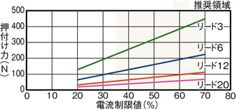
Correlation diagram of pressing force and current limiting value
Adaptive controller
(Note) EC series has their controller built-in themselves. See page 2-392 for details of the built-in controller.
Oversea specification
Important notes on selection
| (1) The value shown for load capacity in "Main specification" refers to the maximum value. When enabling the power saving setting, the main specifications will change. For details, refer to "Payload table by speed/acceleration". (2) Radial cylinder has a built-in guide. See pages 1-295 for detailed information on the radial load acting on the rod. (3) Horizontal load capacity is when using an external guide together. (4) Please refer to "Correlation diagram of pressing force and current limiting value" if you wish to have pressing motions to be carried out. Pressing force shown are their standard value. (5) It is necessary to limit the duty depending on the ambient temperature used. Refer to page 1-280 for further details. (6) The interface box is not dust-proof and drip-proof. Install it in a place where it will not be exposed to water. (7) Safety measures may be required depending on the attachment orientation. Refer to page 1-261 for further details. |
Dimension drawing
ST: Stroke
M.E.: Mechanical end
S.E.: Stroke end
*1 Actuator cable length can be changed to 5m as an option.
*2 The interface box relay section inside the broken line is not dust-proof and drip-proof.
*3 Select the actuator cable and power I/O cable so to have their total length 10m or less.
(Note) The rod moves to the M.E. upon returning to origin, so please take precaution that it may not interfere with anything while the returning process is running.
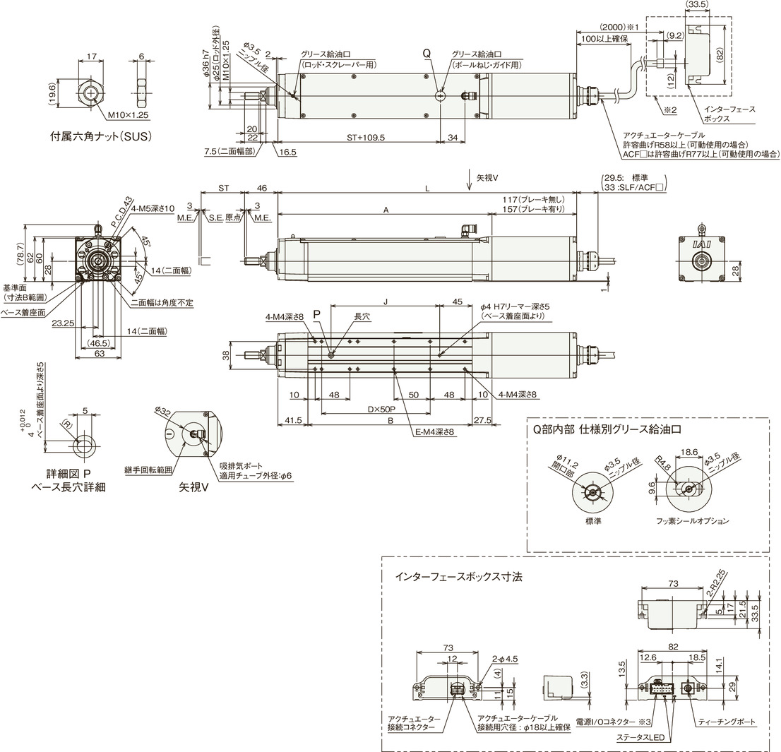
Dimension by stroke length
| Stroke | 65 | 115 | 165 | 215 | 265 | 315 | |
|---|---|---|---|---|---|---|---|
| L | Without brake | 363 | 413 | 463 | 513 | 563 | 613 |
| With brake | 403 | 453 | 503 | 553 | 603 | 653 | |
| A | 246 | 296 | 346 | 396 | 446 | 496 | |
| B | 177 | 227 | 277 | 327 | 377 | 427 | |
| D | 2 | 3 | 4 | 5 | 6 | 7 | |
| E | 4 | 6 | 8 | 10 | 12 | 14 | |
| J | 100 | 150 | 200 | 250 | 300 | 350 | |
Mass by stroke length
| Stroke | 65 | 115 | 165 | 215 | 265 | 315 | |
|---|---|---|---|---|---|---|---|
| Mass (kg) | Without brake | 2.4 | 2.7 | 3.1 | 3.4 | 3.7 | 4.1 |
| With brake | 2.7 | 3 | 3.3 | 3.7 | 4 | 4.3 | |
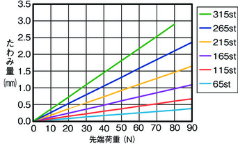
Rod deflection
