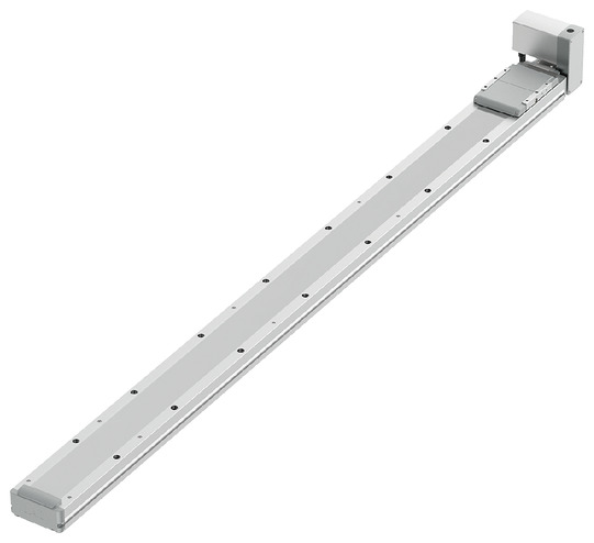
(Note) The photo above shows the top-mounted motor type (SA1L).
Main specification
| Heading | Contents | |||
|---|---|---|---|---|
| Stroke | 200 - 1450 | 1500 - 2600 | ||
| Lead | Lead (mm) | Equivalent to 28 | Equivalent to 28 | |
| Horizontal | Load capacity | Maximum load capacity (kg) (Note 4) | 20 | 15 |
| Speed/ Acceleration/Deceleration | Maximum speed (mm/s) | 2000 | 2000 | |
| Minimum speed (mm/s) | 1.71 | 1.71 | ||
| Rated acceleration/deceleration (G) | 0.3 | 0.3 | ||
| Maximum acceleration/deceleration (G) | 2.0 | 2.0 | ||
| Vertical | Load capacity | Maximum load capacity (kg) | - | - |
| Speed/ Acceleration/Deceleration | Maximum speed (mm/s) | - | - | |
| Minimum speed (mm/s) | - | - | ||
| Rated acceleration/deceleration (G) | - | - | ||
| Maximum acceleration/deceleration (G) | - | - | ||
| Thrust | Rated thrust (N) | 53.5 | 53.5 | |
| Brake | Brake specification | - | - | |
| Brake retention force (kgf) | - | - | ||
| Stroke | Minimum stroke (mm) | 200 | 1500 | |
| Maximum stroke (mm) | 1450 | 2600 | ||
| Stroke pitch (mm) | 50 | 50 | ||
(Note 4) Maximum payload is lower for double slider type (W). Please refer to the table below for details.
| Heading | Contents |
|---|---|
| Drive system | Timing belt, lead 28mm equivalent |
| Accuracy of Repeating Positioning. | ±0.04mm |
| Lost motion | 0.1mm or less |
| Base | Material: White alumite treated aluminum |
| Linear guide | Infinite linear circulation type |
| Static allowable moment (single slider type) | Ma: 109N・m |
| Mb: 156N・m | |
| Mc: 255N・m | |
| Static allowable moment (double slider specification) (Note 5) | Ma: 744N・m |
| Mb: 1060N・m | |
| Mc: 510N・m | |
| Dynamic allowable moment (single slider specification) (Note 6) | Ma: 32.9N・m |
| Mb: 47.0N・m | |
| Mc: 76.8N・m | |
| Dynamic allowable moment (double slider specification) (Note 6) | Ma: Slider actual span minimum [60mm] 182N・m, maximum [90mm] 228N・m |
| Mb: Slider actual span minimum [60mm] 260N・m, maximum [90mm] 325N・m | |
| Mc: Slider actual span minimum [60mm] 125N・m, maximum [90mm] 125N・m | |
| Ambient operating temperature and humidity | 0 - 40℃, RH 85% and below (no condensation) |
| Protection grade | IP20 |
| Vibration resistant/Shock resistant | 4.9m/s2 |
| Compatible to overseas standards | CE mark, RoHS compliant |
| Motor type | AC servo motor |
| Encoder type | Battery-less absolute |
| Encoder pulse No. | 16384 pulse/rev |
| Delivery | Written in [Reference for delivery] section of the homepage |
(Note 5) The value is the same regardless of the slider span.
(Note 6) Based on standard rated life of 10,000km. Life time travelling distance differs based on operating condition and attached condition. Refer page 1-276 for the operating life.
Slider type moment direction

Load capacity by speed and acceleration table
The base unit for load capacity is kilogram (kg).
| Orientation | Horizontal | |||||||||||||||||||
|---|---|---|---|---|---|---|---|---|---|---|---|---|---|---|---|---|---|---|---|---|
| Lead (mm) | Maximum speed (mm/s) | Stroke (mm) | Acceleration (G) | |||||||||||||||||
| 0.3 | 0.4 | 0.5 | 0.6 | 0.7 | 0.8 | 0.9 | 1.0 | 1.1 | 1.2 | 1.3 | 1.4 | 1.5 | 1.6 | 1.7 | 1.8 | 1.9 | 2.0 | |||
| 28 | 2000 | 200 - 1450 | 20 | 15.5 | 12.5 | 10 | 8.5 | 7.5 | 6.5 | 5.5 | 4.7 | 4.3 | 3.9 | 3.5 | 3.2 | 3 | 2.7 | 2.4 | 2.2 | 2 |
| 1500 - 2600 | 15 | 15 | 12.5 | 10 | 8.5 | 7.5 | 6.5 | 5.5 | 4.7 | 4.3 | 3.9 | 3.5 | 3.2 | 3 | 2.7 | 2.4 | 2.2 | 2 | ||
(Note) The controller power supply voltage does not affect the specifications.
Stroke and maximum speed
(Measured in mm/s)
| 200 - 2600 (per 50mm) |
|---|
| 2000 |
Adaptive controller
The actuators introduced in this page are controllable using the controllers shown below. Please select their type based on intended usage.
| Name | Appearance | Max. connectable axis No. | Power source voltage | Control method | Maximum positioning points | ||||||||||||||
|---|---|---|---|---|---|---|---|---|---|---|---|---|---|---|---|---|---|---|---|
| Positioner | Pulse train | Program | Network *Select | ||||||||||||||||
| DV | CC | CIE | PR | CN | ML | ML3 | EC | EP | PRT | SSN | ECM | ||||||||
| RCON |  | 16 (ML3,SSN,ECM is 8) | DC24V, single phase AC200V, three phase AC200V | - | - | - | ● | ● | ● | ● | - | - | ● | ● | ● | ● | ● | ● | 128 (Position data unavailable for ML3, SSN and ECM) |
| RSEL | 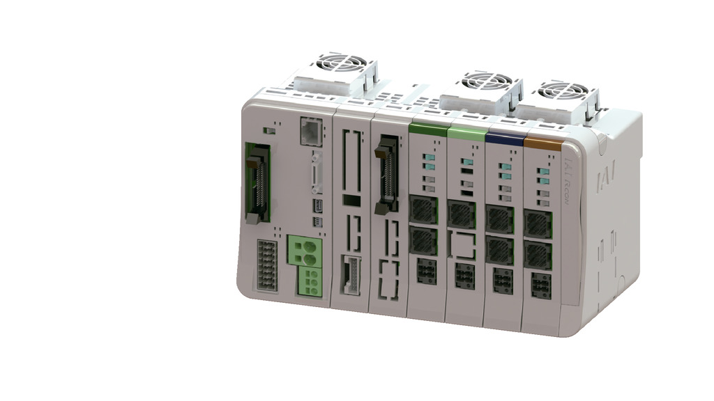 | 8 | - | - | ● | ● | ● | ● | ● | - | - | - | ● | ● | ● | - | - | 36000 | |
| SCON-CB/CGB | 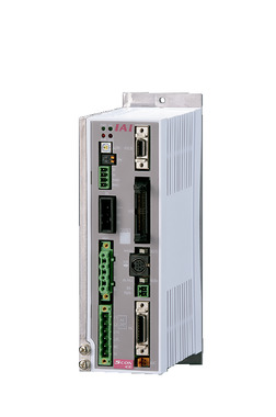 | 1 | Single phase AC 100V/ 200V | ● | ● | - | ● | ● | ● | ● | ● | ● | ● | ● | ● | ● | - | ● | 512 (768 for network specification) |
| SCON2-CG |  | 1 | Single phase AC100V | ● | ● | - | ● | ● | ● | - | - | - | ● | ● | ● | ● | - | - | 384 |
| SCON2-CG |  | 1 | Single phase AC200V | ● | ● | - | ● | ● | ● | - | - | - | ● | ● | ● | ● | - | - | 384 |
| XSEL-P/Q | 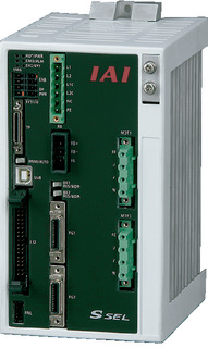 | 6 | Single phase AC200V Three-phase AC200V | - | - | ● | ● | ● | - | ● | - | - | - | - | ● | - | - | - | 20000 |
| XSEL-RA/SA | 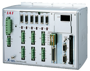 | 8 | - | - | ● | ● | ● | ● | ● | - | - | - | ● | ● | - | - | - | 55000 (Vary based on type) | |
(Note) For network abbreviations such as DV and CC, please refer to page 8-15.
(Note) For SCON2 ML3 and EC, if you do not specify the controller model function option, it will be a remote I/O specification, and if you select "M", it will be a motion network specification.
Oversea specification
Important notes on selection
| (1) You will need extra care based on the installed orientation. Refer to page 1-307 for further details. (2) The load capacity shown in the "Main specification" refers to their maximum value. Please refer to the "Table of payload by speed/acceleration" for further details. (3) Pressing motion can't be carried out as well. (4) The guideline for the usable duty ratio changes depending on the load factor. Refer to page 1-328 for further details. (5) The center of gravity of the mounted object should be 1/2 or less of the overhang distance. Even if the overhang distance and load moment are within the allowable values, if abnormal vibration or noise occurs during operation, loosen the operating conditions before use. (6) The approximate overhang load length is 450 mm or less in Ma, Mb, and Mc directions (for double slider types, the minimum actual slider span [60 mm]: 1200mm, maximum [90mm]: 1350mm or less). Please refer to page 3-52 for the overhang load length. (7) Please refer to page 1-293 for the ordering model number and precautions when selecting the double slider type. |
Dimension drawing
IFA-SA1 (top-mounted motor)
ST: Stroke
M.E.: Mechanical end
S.E.: Stroke end
(Note) The cable joint connector shall have motor cable and encoder cable connected to it. Please refer to page 3-711 for the cable details.
(Note) Please be careful while returning to the home position, for there is a chance of collision while having the slider returning to the M.E. position.
(Note) Please take note that return setting has to be adjusted to change the originating direction.
(Note) The figure below is SA1L.
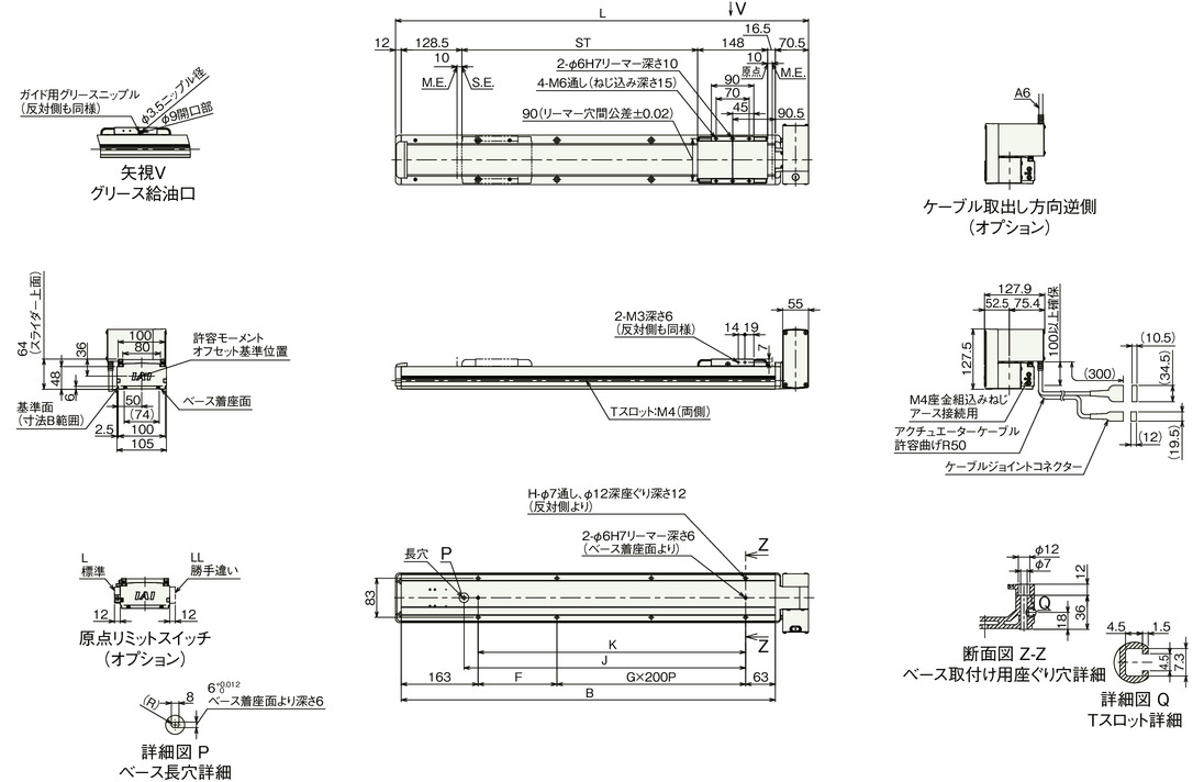
Dimension by stroke length
| Stroke | 200 | 250 | 300 | 350 | 400 | 450 | 500 | 550 | 600 | 650 | 700 | 750 | 800 | 850 | 900 | 950 | 1000 | 1050 | 1100 | 1150 | 1200 | 1250 | 1300 | 1350 | 1400 |
|---|---|---|---|---|---|---|---|---|---|---|---|---|---|---|---|---|---|---|---|---|---|---|---|---|---|
| L | 575.5 | 625.5 | 675.5 | 725.5 | 775.5 | 825.5 | 875.5 | 925.5 | 975.5 | 1025.5 | 1075.5 | 1125.5 | 1175.5 | 1225.5 | 1275.5 | 1325.5 | 1375.5 | 1425.5 | 1475.5 | 1525.5 | 1575.5 | 1625.5 | 1675.5 | 1725.5 | 1775.5 |
| B | 493 | 543 | 593 | 643 | 693 | 743 | 793 | 843 | 893 | 943 | 993 | 1043 | 1093 | 1143 | 1193 | 1243 | 1293 | 1343 | 1393 | 1443 | 1493 | 1543 | 1593 | 1643 | 1693 |
| F | 67 | 117 | 167 | 217 | 67 | 117 | 167 | 217 | 67 | 117 | 167 | 217 | 67 | 117 | 167 | 217 | 67 | 117 | 167 | 217 | 67 | 117 | 167 | 217 | 67 |
| G | 1 | 1 | 1 | 1 | 2 | 2 | 2 | 2 | 3 | 3 | 3 | 3 | 4 | 4 | 4 | 4 | 5 | 5 | 5 | 5 | 6 | 6 | 6 | 6 | 7 |
| H | 6 | 6 | 6 | 6 | 8 | 8 | 8 | 8 | 10 | 10 | 10 | 10 | 12 | 12 | 12 | 12 | 14 | 14 | 14 | 14 | 16 | 16 | 16 | 16 | 18 |
| J | 297 | 347 | 397 | 447 | 497 | 547 | 597 | 647 | 697 | 747 | 797 | 847 | 897 | 947 | 997 | 1047 | 1097 | 1147 | 1197 | 1247 | 1297 | 1347 | 1397 | 1447 | 1497 |
| K | 267 | 317 | 367 | 417 | 467 | 517 | 567 | 617 | 667 | 717 | 767 | 817 | 867 | 917 | 967 | 1017 | 1067 | 1117 | 1167 | 1217 | 1267 | 1317 | 1367 | 1417 | 1467 |
Dimension by stroke length
| Stroke | 1450 | 1500 | 1550 | 1600 | 1650 | 1700 | 1750 | 1800 | 1850 | 1900 | 1950 | 2000 | 2050 | 2100 | 2150 | 2200 | 2250 | 2300 | 2350 | 2400 | 2450 | 2500 | 2550 | 2600 |
|---|---|---|---|---|---|---|---|---|---|---|---|---|---|---|---|---|---|---|---|---|---|---|---|---|
| L | 1825.5 | 1875.5 | 1925.5 | 1975.5 | 2025.5 | 2075.5 | 2125.5 | 2175.5 | 2225.5 | 2275.5 | 2325.5 | 2375.5 | 2425.5 | 2475.5 | 2525.5 | 2575.5 | 2625.5 | 2675.5 | 2725.5 | 2775.5 | 2825.5 | 2875.5 | 2925.5 | 2975.5 |
| B | 1743 | 1793 | 1843 | 1893 | 1943 | 1993 | 2043 | 2093 | 2143 | 2193 | 2243 | 2293 | 2343 | 2393 | 2443 | 2493 | 2543 | 2593 | 2643 | 2693 | 2743 | 2793 | 2843 | 2893 |
| F | 117 | 167 | 217 | 67 | 117 | 167 | 217 | 67 | 117 | 167 | 217 | 67 | 117 | 167 | 217 | 67 | 117 | 167 | 217 | 67 | 117 | 167 | 217 | 67 |
| G | 7 | 7 | 7 | 8 | 8 | 8 | 8 | 9 | 9 | 9 | 9 | 10 | 10 | 10 | 10 | 11 | 11 | 11 | 11 | 12 | 12 | 12 | 12 | 13 |
| H | 18 | 18 | 18 | 20 | 20 | 20 | 20 | 22 | 22 | 22 | 22 | 24 | 24 | 24 | 24 | 26 | 26 | 26 | 26 | 28 | 28 | 28 | 28 | 30 |
| J | 1547 | 1597 | 1647 | 1697 | 1747 | 1797 | 1847 | 1897 | 1947 | 1997 | 2047 | 2097 | 2147 | 2197 | 2247 | 2297 | 2347 | 2397 | 2447 | 2497 | 2547 | 2597 | 2647 | 2697 |
| K | 1517 | 1567 | 1617 | 1667 | 1717 | 1767 | 1817 | 1867 | 1917 | 1967 | 2017 | 2067 | 2117 | 2167 | 2217 | 2267 | 2317 | 2367 | 2417 | 2467 | 2517 | 2567 | 2617 | 2667 |
Mass by stroke length
| Stroke | 200 | 250 | 300 | 350 | 400 | 450 | 500 | 550 | 600 | 650 | 700 | 750 | 800 | 850 | 900 | 950 | 1000 | 1050 | 1100 | 1150 | 1200 | 1250 | 1300 | 1350 | 1400 |
|---|---|---|---|---|---|---|---|---|---|---|---|---|---|---|---|---|---|---|---|---|---|---|---|---|---|
| Mass (kg) | 6.0 | 6.3 | 6.6 | 7.0 | 7.3 | 7.6 | 7.9 | 8.3 | 8.6 | 8.9 | 9.2 | 9.5 | 9.9 | 10.2 | 10.5 | 10.8 | 11.2 | 11.5 | 11.8 | 12.1 | 12.4 | 12.8 | 13.1 | 13.4 | 13.7 |
Mass by stroke length
| Stroke | 1450 | 1500 | 1550 | 1600 | 1650 | 1700 | 1750 | 1800 | 1850 | 1900 | 1950 | 2000 | 2050 | 2100 | 2150 | 2200 | 2250 | 2300 | 2350 | 2400 | 2450 | 2500 | 2550 | 2600 |
|---|---|---|---|---|---|---|---|---|---|---|---|---|---|---|---|---|---|---|---|---|---|---|---|---|
| Mass (kg) | 14.1 | 14.4 | 14.7 | 15.0 | 15.4 | 15.7 | 16.0 | 16.3 | 16.7 | 17.0 | 17.3 | 17.6 | 17.9 | 18.3 | 18.6 | 18.9 | 19.2 | 19.6 | 19.9 | 20.2 | 20.5 | 20.9 | 21.2 | 21.5 |
IFA-SA2 (side-mounted motor)
ST: Stroke
M.E.: Mechanical end
S.E.: Stroke end
(Note) The cable joint connector shall have motor cable and encoder cable connected to it. Please refer to page 3-711 for the cable details.
(Note) Please be careful while returning to the home position, for there is a chance of collision while having the slider returning to the M.E. position.
(Note) Please take note that return setting has to be adjusted to change the originating direction.
(Note) The figure below is SA2L.
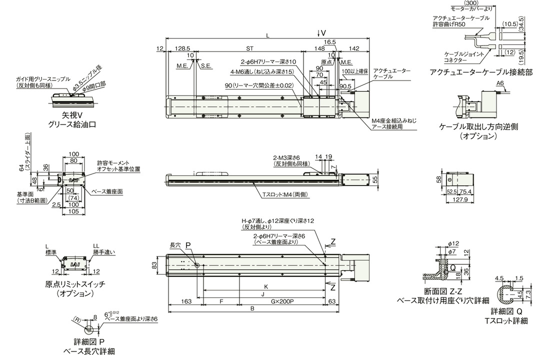
Dimension by stroke length
| Stroke | 200 | 250 | 300 | 350 | 400 | 450 | 500 | 550 | 600 | 650 | 700 | 750 | 800 | 850 | 900 | 950 | 1000 | 1050 | 1100 | 1150 | 1200 | 1250 | 1300 | 1350 | 1400 |
|---|---|---|---|---|---|---|---|---|---|---|---|---|---|---|---|---|---|---|---|---|---|---|---|---|---|
| L | 647 | 697 | 747 | 797 | 847 | 897 | 947 | 997 | 1047 | 1097 | 1147 | 1197 | 1247 | 1297 | 1347 | 1397 | 1447 | 1497 | 1547 | 1597 | 1647 | 1697 | 1747 | 1797 | 1847 |
| B | 493 | 543 | 593 | 643 | 693 | 743 | 793 | 843 | 893 | 943 | 993 | 1043 | 1093 | 1143 | 1193 | 1243 | 1293 | 1343 | 1393 | 1443 | 1493 | 1543 | 1593 | 1643 | 1693 |
| F | 67 | 117 | 167 | 217 | 67 | 117 | 167 | 217 | 67 | 117 | 167 | 217 | 67 | 117 | 167 | 217 | 67 | 117 | 167 | 217 | 67 | 117 | 167 | 217 | 67 |
| G | 1 | 1 | 1 | 1 | 2 | 2 | 2 | 2 | 3 | 3 | 3 | 3 | 4 | 4 | 4 | 4 | 5 | 5 | 5 | 5 | 6 | 6 | 6 | 6 | 7 |
| H | 6 | 6 | 6 | 6 | 8 | 8 | 8 | 8 | 10 | 10 | 10 | 10 | 12 | 12 | 12 | 12 | 14 | 14 | 14 | 14 | 16 | 16 | 16 | 16 | 18 |
| J | 297 | 347 | 397 | 447 | 497 | 547 | 597 | 647 | 697 | 747 | 797 | 847 | 897 | 947 | 997 | 1047 | 1097 | 1147 | 1197 | 1247 | 1297 | 1347 | 1397 | 1447 | 1497 |
| K | 267 | 317 | 367 | 417 | 467 | 517 | 567 | 617 | 667 | 717 | 767 | 817 | 867 | 917 | 967 | 1017 | 1067 | 1117 | 1167 | 1217 | 1267 | 1317 | 1367 | 1417 | 1467 |
Dimension by stroke length
| Stroke | 1450 | 1500 | 1550 | 1600 | 1650 | 1700 | 1750 | 1800 | 1850 | 1900 | 1950 | 2000 | 2050 | 2100 | 2150 | 2200 | 2250 | 2300 | 2350 | 2400 | 2450 | 2500 | 2550 | 2600 |
|---|---|---|---|---|---|---|---|---|---|---|---|---|---|---|---|---|---|---|---|---|---|---|---|---|
| L | 1897 | 1947 | 1997 | 2047 | 2097 | 2147 | 2197 | 2247 | 2297 | 2347 | 2397 | 2447 | 2497 | 2547 | 2597 | 2647 | 2697 | 2747 | 2797 | 2847 | 2897 | 2947 | 2997 | 3047 |
| B | 1743 | 1793 | 1843 | 1893 | 1943 | 1993 | 2043 | 2093 | 2143 | 2193 | 2243 | 2293 | 2343 | 2393 | 2443 | 2493 | 2543 | 2593 | 2643 | 2693 | 2743 | 2793 | 2843 | 2893 |
| F | 117 | 167 | 217 | 67 | 117 | 167 | 217 | 67 | 117 | 167 | 217 | 67 | 117 | 167 | 217 | 67 | 117 | 167 | 217 | 67 | 117 | 167 | 217 | 67 |
| G | 7 | 7 | 7 | 8 | 8 | 8 | 8 | 9 | 9 | 9 | 9 | 10 | 10 | 10 | 10 | 11 | 11 | 11 | 11 | 12 | 12 | 12 | 12 | 13 |
| H | 18 | 18 | 18 | 20 | 20 | 20 | 20 | 22 | 22 | 22 | 22 | 24 | 24 | 24 | 24 | 26 | 26 | 26 | 26 | 28 | 28 | 28 | 28 | 30 |
| J | 1547 | 1597 | 1647 | 1697 | 1747 | 1797 | 1847 | 1897 | 1947 | 1997 | 2047 | 2097 | 2147 | 2197 | 2247 | 2297 | 2347 | 2397 | 2447 | 2497 | 2547 | 2597 | 2647 | 2697 |
| K | 1517 | 1567 | 1617 | 1667 | 1717 | 1767 | 1817 | 1867 | 1917 | 1967 | 2017 | 2067 | 2117 | 2167 | 2217 | 2267 | 2317 | 2367 | 2417 | 2467 | 2517 | 2567 | 2617 | 2667 |
Mass by stroke length
| Stroke | 200 | 250 | 300 | 350 | 400 | 450 | 500 | 550 | 600 | 650 | 700 | 750 | 800 | 850 | 900 | 950 | 1000 | 1050 | 1100 | 1150 | 1200 | 1250 | 1300 | 1350 | 1400 |
|---|---|---|---|---|---|---|---|---|---|---|---|---|---|---|---|---|---|---|---|---|---|---|---|---|---|
| Mass (kg) | 6.0 | 6.3 | 6.6 | 7.0 | 7.3 | 7.6 | 7.9 | 8.3 | 8.6 | 8.9 | 9.2 | 9.5 | 9.9 | 10.2 | 10.5 | 10.8 | 11.2 | 11.5 | 11.8 | 12.1 | 12.4 | 12.8 | 13.1 | 13.4 | 13.7 |
Mass by stroke length
| Stroke | 1450 | 1500 | 1550 | 1600 | 1650 | 1700 | 1750 | 1800 | 1850 | 1900 | 1950 | 2000 | 2050 | 2100 | 2150 | 2200 | 2250 | 2300 | 2350 | 2400 | 2450 | 2500 | 2550 | 2600 |
|---|---|---|---|---|---|---|---|---|---|---|---|---|---|---|---|---|---|---|---|---|---|---|---|---|
| Mass (kg) | 14.1 | 14.4 | 14.7 | 15.0 | 15.4 | 15.7 | 16.0 | 16.3 | 16.7 | 17.0 | 17.3 | 17.6 | 17.9 | 18.3 | 18.6 | 18.9 | 19.2 | 19.6 | 19.9 | 20.2 | 20.5 | 20.9 | 21.2 | 21.5 |
IFA-SA3 (bottom-mounted motor)
ST: Stroke
M.E.: Mechanical end
S.E.: Stroke end
(Note) The cable joint connector shall have motor cable and encoder cable connected to it. Please refer to page 3-711 for the cable details.
(Note) Please be careful while returning to the home position, for there is a chance of collision while having the slider returning to the M.E. position.
(Note) Please take note that return setting has to be adjusted to change the originating direction.
(Note) The figure below is SA3L.
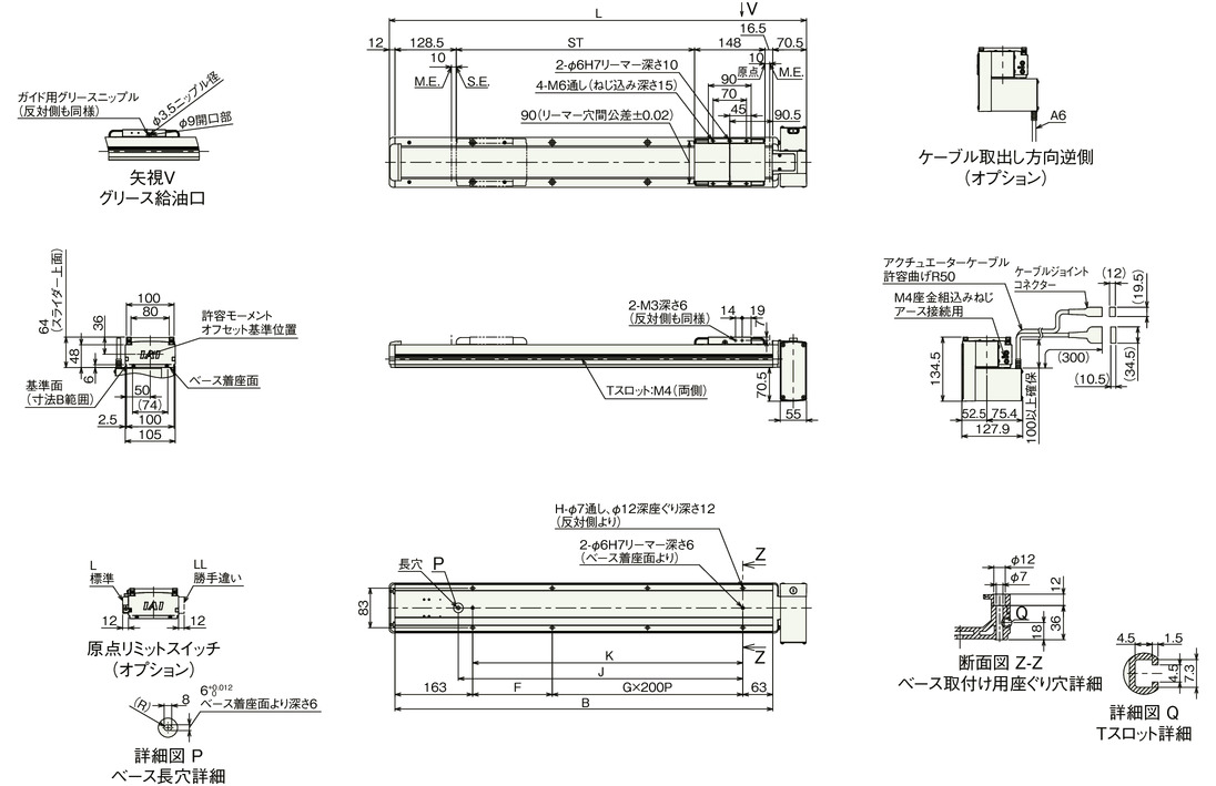
Dimension by stroke length
| Stroke | 200 | 250 | 300 | 350 | 400 | 450 | 500 | 550 | 600 | 650 | 700 | 750 | 800 | 850 | 900 | 950 | 1000 | 1050 | 1100 | 1150 | 1200 | 1250 | 1300 | 1350 | 1400 |
|---|---|---|---|---|---|---|---|---|---|---|---|---|---|---|---|---|---|---|---|---|---|---|---|---|---|
| L | 575.5 | 625.5 | 675.5 | 725.5 | 775.5 | 825.5 | 875.5 | 925.5 | 975.5 | 1025.5 | 1075.5 | 1125.5 | 1175.5 | 1225.5 | 1275.5 | 1325.5 | 1375.5 | 1425.5 | 1475.5 | 1525.5 | 1575.5 | 1625.5 | 1675.5 | 1725.5 | 1775.5 |
| B | 493 | 543 | 593 | 643 | 693 | 743 | 793 | 843 | 893 | 943 | 993 | 1043 | 1093 | 1143 | 1193 | 1243 | 1293 | 1343 | 1393 | 1443 | 1493 | 1543 | 1593 | 1643 | 1693 |
| F | 67 | 117 | 167 | 217 | 67 | 117 | 167 | 217 | 67 | 117 | 167 | 217 | 67 | 117 | 167 | 217 | 67 | 117 | 167 | 217 | 67 | 117 | 167 | 217 | 67 |
| G | 1 | 1 | 1 | 1 | 2 | 2 | 2 | 2 | 3 | 3 | 3 | 3 | 4 | 4 | 4 | 4 | 5 | 5 | 5 | 5 | 6 | 6 | 6 | 6 | 7 |
| H | 6 | 6 | 6 | 6 | 8 | 8 | 8 | 8 | 10 | 10 | 10 | 10 | 12 | 12 | 12 | 12 | 14 | 14 | 14 | 14 | 16 | 16 | 16 | 16 | 18 |
| J | 297 | 347 | 397 | 447 | 497 | 547 | 597 | 647 | 697 | 747 | 797 | 847 | 897 | 947 | 997 | 1047 | 1097 | 1147 | 1197 | 1247 | 1297 | 1347 | 1397 | 1447 | 1497 |
| K | 267 | 317 | 367 | 417 | 467 | 517 | 567 | 617 | 667 | 717 | 767 | 817 | 867 | 917 | 967 | 1017 | 1067 | 1117 | 1167 | 1217 | 1267 | 1317 | 1367 | 1417 | 1467 |
Dimension by stroke length
| Stroke | 1450 | 1500 | 1550 | 1600 | 1650 | 1700 | 1750 | 1800 | 1850 | 1900 | 1950 | 2000 | 2050 | 2100 | 2150 | 2200 | 2250 | 2300 | 2350 | 2400 | 2450 | 2500 | 2550 | 2600 |
|---|---|---|---|---|---|---|---|---|---|---|---|---|---|---|---|---|---|---|---|---|---|---|---|---|
| L | 1825.5 | 1875.5 | 1925.5 | 1975.5 | 2025.5 | 2075.5 | 2125.5 | 2175.5 | 2225.5 | 2275.5 | 2325.5 | 2375.5 | 2425.5 | 2475.5 | 2525.5 | 2575.5 | 2625.5 | 2675.5 | 2725.5 | 2775.5 | 2825.5 | 2875.5 | 2925.5 | 2975.5 |
| B | 1743 | 1793 | 1843 | 1893 | 1943 | 1993 | 2043 | 2093 | 2143 | 2193 | 2243 | 2293 | 2343 | 2393 | 2443 | 2493 | 2543 | 2593 | 2643 | 2693 | 2743 | 2793 | 2843 | 2893 |
| F | 117 | 167 | 217 | 67 | 117 | 167 | 217 | 67 | 117 | 167 | 217 | 67 | 117 | 167 | 217 | 67 | 117 | 167 | 217 | 67 | 117 | 167 | 217 | 67 |
| G | 7 | 7 | 7 | 8 | 8 | 8 | 8 | 9 | 9 | 9 | 9 | 10 | 10 | 10 | 10 | 11 | 11 | 11 | 11 | 12 | 12 | 12 | 12 | 13 |
| H | 18 | 18 | 18 | 20 | 20 | 20 | 20 | 22 | 22 | 22 | 22 | 24 | 24 | 24 | 24 | 26 | 26 | 26 | 26 | 28 | 28 | 28 | 28 | 30 |
| J | 1547 | 1597 | 1647 | 1697 | 1747 | 1797 | 1847 | 1897 | 1947 | 1997 | 2047 | 2097 | 2147 | 2197 | 2247 | 2297 | 2347 | 2397 | 2447 | 2497 | 2547 | 2597 | 2647 | 2697 |
| K | 1517 | 1567 | 1617 | 1667 | 1717 | 1767 | 1817 | 1867 | 1917 | 1967 | 2017 | 2067 | 2117 | 2167 | 2217 | 2267 | 2317 | 2367 | 2417 | 2467 | 2517 | 2567 | 2617 | 2667 |
Mass by stroke length
| Stroke | 200 | 250 | 300 | 350 | 400 | 450 | 500 | 550 | 600 | 650 | 700 | 750 | 800 | 850 | 900 | 950 | 1000 | 1050 | 1100 | 1150 | 1200 | 1250 | 1300 | 1350 | 1400 |
|---|---|---|---|---|---|---|---|---|---|---|---|---|---|---|---|---|---|---|---|---|---|---|---|---|---|
| Mass (kg) | 6.0 | 6.3 | 6.6 | 7.0 | 7.3 | 7.6 | 7.9 | 8.3 | 8.6 | 8.9 | 9.2 | 9.5 | 9.9 | 10.2 | 10.5 | 10.8 | 11.2 | 11.5 | 11.8 | 12.1 | 12.4 | 12.8 | 13.1 | 13.4 | 13.7 |
Mass by stroke length
| Stroke | 1450 | 1500 | 1550 | 1600 | 1650 | 1700 | 1750 | 1800 | 1850 | 1900 | 1950 | 2000 | 2050 | 2100 | 2150 | 2200 | 2250 | 2300 | 2350 | 2400 | 2450 | 2500 | 2550 | 2600 |
|---|---|---|---|---|---|---|---|---|---|---|---|---|---|---|---|---|---|---|---|---|---|---|---|---|
| Mass (kg) | 14.1 | 14.4 | 14.7 | 15.0 | 15.4 | 15.7 | 16.0 | 16.3 | 16.7 | 17.0 | 17.3 | 17.6 | 17.9 | 18.3 | 18.6 | 18.9 | 19.2 | 19.6 | 19.9 | 20.2 | 20.5 | 20.9 | 21.2 | 21.5 |
Payload table by speed/acceleration (double slider type)
The base unit for load capacity is kilogram (kg). Empty column refers to inoperable motion.
| Orientation | Horizontal | |||||||||||||||||||
|---|---|---|---|---|---|---|---|---|---|---|---|---|---|---|---|---|---|---|---|---|
| Lead (mm) | Maximum speed (mm/s) | Nominal stroke (mm) | Acceleration (G) | |||||||||||||||||
| 0.3 | 0.4 | 0.5 | 0.6 | 0.7 | 0.8 | 0.9 | 1.0 | 1.1 | 1.2 | 1.3 | 1.4 | 1.5 | 1.6 | 1.7 | 1.8 | 1.9 | 2.0 | |||
| 28 | 2000 | 350 - 1450 | 18 | 13.5 | 10.5 | 8 | 6.5 | 5.5 | 4.5 | 3.5 | 2.7 | 2.3 | 1.9 | 1.5 | 1.2 | 1 | 0.7 | 0.4 | 0.2 | |
| 1500 - 2600 | 13 | 13 | 10.5 | 8 | 6.5 | 5.5 | 4.5 | 3.5 | 2.7 | 2.3 | 1.9 | 1.5 | 1.2 | 1 | 0.7 | 0.4 | 0.2 | |||
(Note) Nominal stroke: This refers to the stroke in the model number, not the actual stroke that can be operated (effective stroke)
(Note) The controller power supply voltage does not affect the specifications.
Dimension drawing (double slider type)
ST: Stroke
M.E.: Mechanical end
S.E.: Stroke end
Drawing (double slider type)
(Note) The cable joint connector shall have motor cable and encoder cable connected to it. Please refer to page 3-711 for the cable details.
(Note) Please be careful while returning to the home position, for there is a chance of collision while having the slider returning to the M.E. position.
(Note) Please take note that return setting has to be adjusted to change the originating direction.
(Note) The figure below is SA1L.
(Note) The figure below shows the dimensions when the actual slider span is the minimum.
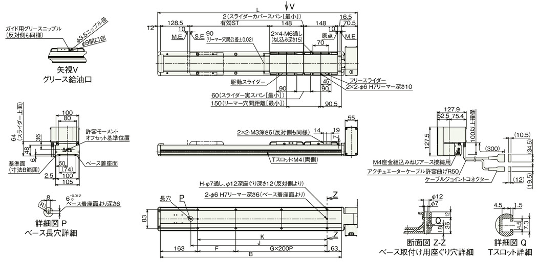
Dimension by stroke length
| Call stroke | 350 | 400 | 450 | 500 | 550 | 600 | 650 | 700 | 750 | 800 | 850 | 900 | 950 | 1000 | 1050 | 1100 | 1150 | 1200 | 1250 | 1300 | 1350 | 1400 | 1450 | |
|---|---|---|---|---|---|---|---|---|---|---|---|---|---|---|---|---|---|---|---|---|---|---|---|---|
| Effective stroke | Slider actual span minimum [60mm] | 200 | 250 | 300 | 350 | 400 | 450 | 500 | 550 | 600 | 650 | 700 | 750 | 800 | 850 | 900 | 950 | 1000 | 1050 | 1100 | 1150 | 1200 | 1250 | 1300 |
| Max. actual span of the slider [90mm] | - | 220 | 270 | 320 | 370 | 420 | 470 | 520 | 570 | 620 | 670 | 720 | 770 | 820 | 870 | 920 | 970 | 1020 | 1070 | 1120 | 1170 | 1220 | 1270 | |
| L | 725.5 | 775.5 | 825.5 | 875.5 | 925.5 | 975.5 | 1025.5 | 1075.5 | 1125.5 | 1175.5 | 1225.5 | 1275.5 | 1325.5 | 1375.5 | 1425.5 | 1475.5 | 1525.5 | 1575.5 | 1625.5 | 1675.5 | 1725.5 | 1775.5 | 1825.5 | |
| B | 643 | 693 | 743 | 793 | 843 | 893 | 943 | 993 | 1043 | 1093 | 1143 | 1193 | 1243 | 1293 | 1343 | 1393 | 1443 | 1493 | 1543 | 1593 | 1643 | 1693 | 1743 | |
| F | 217 | 67 | 117 | 167 | 217 | 67 | 117 | 167 | 217 | 67 | 117 | 167 | 217 | 67 | 117 | 167 | 217 | 67 | 117 | 167 | 217 | 67 | 117 | |
| G | 1 | 2 | 2 | 2 | 2 | 3 | 3 | 3 | 3 | 4 | 4 | 4 | 4 | 5 | 5 | 5 | 5 | 6 | 6 | 6 | 6 | 7 | 7 | |
| H | 6 | 8 | 8 | 8 | 8 | 10 | 10 | 10 | 10 | 12 | 12 | 12 | 12 | 14 | 14 | 14 | 14 | 16 | 16 | 16 | 16 | 18 | 18 | |
| J | 447 | 497 | 547 | 597 | 647 | 697 | 747 | 797 | 847 | 897 | 947 | 997 | 1047 | 1097 | 1147 | 1197 | 1247 | 1297 | 1347 | 1397 | 1447 | 1497 | 1547 | |
| K | 417 | 467 | 517 | 567 | 617 | 667 | 717 | 767 | 817 | 867 | 917 | 967 | 1017 | 1067 | 1117 | 1167 | 1217 | 1267 | 1317 | 1367 | 1417 | 1467 | 1517 | |
Dimensions by stroke (double slider type)
| Call stroke | 1500 | 1550 | 1600 | 1650 | 1700 | 1750 | 1800 | 1850 | 1900 | 1950 | 2000 | 2050 | 2100 | 2150 | 2200 | 2250 | 2300 | 2350 | 2400 | 2450 | 2500 | 2550 | 2600 | |
|---|---|---|---|---|---|---|---|---|---|---|---|---|---|---|---|---|---|---|---|---|---|---|---|---|
| Effective stroke | Slider actual span minimum [60mm] | 1350 | 1400 | 1450 | 1500 | 1550 | 1600 | 1650 | 1700 | 1750 | 1800 | 1850 | 1900 | 1950 | 2000 | 2050 | 2100 | 2150 | 2200 | 2250 | 2300 | 2350 | 2400 | 2450 |
| Max. actual span of the slider [90mm] | 1320 | 1370 | 1420 | 1470 | 1520 | 1570 | 1620 | 1670 | 1720 | 1770 | 1820 | 1870 | 1920 | 1970 | 2020 | 2070 | 2120 | 2170 | 2220 | 2270 | 2320 | 2370 | 2420 | |
| L | 1875.5 | 1925.5 | 1975.5 | 2025.5 | 2075.5 | 2125.5 | 2175.5 | 2225.5 | 2275.5 | 2325.5 | 2375.5 | 2425.5 | 2475.5 | 2525.5 | 2575.5 | 2625.5 | 2675.5 | 2725.5 | 2775.5 | 2825.5 | 2875.5 | 2925.5 | 2975.5 | |
| B | 1793 | 1843 | 1893 | 1943 | 1993 | 2043 | 2093 | 2143 | 2193 | 2243 | 2293 | 2343 | 2393 | 2443 | 2493 | 2543 | 2593 | 2643 | 2693 | 2743 | 2793 | 2843 | 2893 | |
| F | 167 | 217 | 67 | 117 | 167 | 217 | 67 | 117 | 167 | 217 | 67 | 117 | 167 | 217 | 67 | 117 | 167 | 217 | 67 | 117 | 167 | 217 | 67 | |
| G | 7 | 7 | 8 | 8 | 8 | 8 | 9 | 9 | 9 | 9 | 10 | 10 | 10 | 10 | 11 | 11 | 11 | 11 | 12 | 12 | 12 | 12 | 13 | |
| H | 18 | 18 | 20 | 20 | 20 | 20 | 22 | 22 | 22 | 22 | 24 | 24 | 24 | 24 | 26 | 26 | 26 | 26 | 28 | 28 | 28 | 28 | 30 | |
| J | 1597 | 1647 | 1697 | 1747 | 1797 | 1847 | 1897 | 1947 | 1997 | 2047 | 2097 | 2147 | 2197 | 2247 | 2297 | 2347 | 2397 | 2447 | 2497 | 2547 | 2597 | 2647 | 2697 | |
| K | 1567 | 1617 | 1667 | 1717 | 1767 | 1817 | 1867 | 1917 | 1967 | 2017 | 2067 | 2117 | 2167 | 2217 | 2267 | 2317 | 2367 | 2417 | 2467 | 2517 | 2567 | 2617 | 2667 | |
(Note) Nominal stroke Stroke in model number Effective stroke: Actual stroke during operation
Mass by stroke length
| Call stroke | 350 | 400 | 450 | 500 | 550 | 600 | 650 | 700 | 750 | 800 | 850 | 900 | 950 | 1000 | 1050 | 1100 | 1150 | 1200 | 1250 | 1300 | 1350 | 1400 | 1450 | |
|---|---|---|---|---|---|---|---|---|---|---|---|---|---|---|---|---|---|---|---|---|---|---|---|---|
| Effective stroke | Slider actual span minimum [60mm] | 200 | 250 | 300 | 350 | 400 | 450 | 500 | 550 | 600 | 650 | 700 | 750 | 800 | 850 | 900 | 950 | 1000 | 1050 | 1100 | 1150 | 1200 | 1250 | 1300 |
| Max. actual span of the slider [90mm] | - | 220 | 270 | 320 | 370 | 420 | 470 | 520 | 570 | 620 | 670 | 720 | 770 | 820 | 870 | 920 | 970 | 1020 | 1070 | 1120 | 1170 | 1220 | 1270 | |
| Mass (kg) | 7.7 | 8.0 | 8.3 | 8.6 | 9.0 | 9.3 | 9.6 | 9.9 | 10.2 | 10.6 | 10.9 | 11.2 | 11.5 | 11.9 | 12.2 | 12.5 | 12.8 | 13.1 | 13.5 | 13.8 | 14.1 | 14.4 | 14.8 | |
Mass by stroke (double slider type)
| Call stroke | 1500 | 1550 | 1600 | 1650 | 1700 | 1750 | 1800 | 1850 | 1900 | 1950 | 2000 | 2050 | 2100 | 2150 | 2200 | 2250 | 2300 | 2350 | 2400 | 2450 | 2500 | 2550 | 2600 | |
|---|---|---|---|---|---|---|---|---|---|---|---|---|---|---|---|---|---|---|---|---|---|---|---|---|
| Effective stroke | Slider actual span minimum [60mm] | 1350 | 1400 | 1450 | 1500 | 1550 | 1600 | 1650 | 1700 | 1750 | 1800 | 1850 | 1900 | 1950 | 2000 | 2050 | 2100 | 2150 | 2200 | 2250 | 2300 | 2350 | 2400 | 2450 |
| Max. actual span of the slider [90mm] | 1320 | 1370 | 1420 | 1470 | 1520 | 1570 | 1620 | 1670 | 1720 | 1770 | 1820 | 1870 | 1920 | 1970 | 2020 | 2070 | 2120 | 2170 | 2220 | 2270 | 2320 | 2370 | 2420 | |
| Mass (kg) | 15.1 | 15.4 | 15.7 | 16.1 | 16.4 | 16.7 | 17.0 | 17.4 | 17.7 | 18.0 | 18.3 | 18.6 | 19.0 | 19.3 | 19.6 | 19.9 | 20.3 | 20.6 | 20.9 | 21.2 | 21.6 | 21.9 | 22.2 | |
(Note) Mass is the single slider specification plus 0.7kg of free slider.


