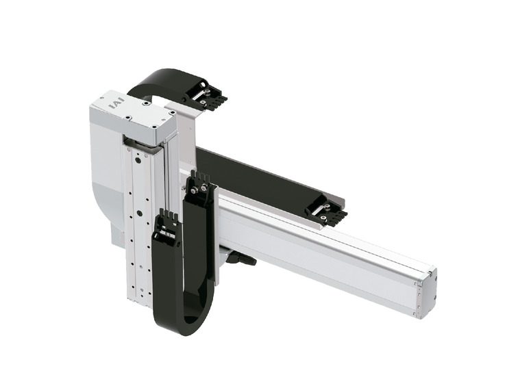
(Note) The above photo shows the configuration direction "1" and the cable track for both the first and second wiring.
For other configuration directions, see page 4-18.
Spec
| Heading | Y axis | Z axis | |
|---|---|---|---|
| Component axis | RCP6-SA8R | RCP6-TA7R | |
| Stroke | 50 - 1100mm (Every 50mm) | 50~200 (Every 25mm), 250, 300mm | |
| Maximum speed (Note 1) | HL | 400mm/s | 140mm/s |
| HM | 280mm/s | ||
| SH | 650mm/s | 420mm/s | |
| Motor size | 56□high thrust pulse motor | 56□ pulse motor | |
| Ball screw lead | HL | 20mm | 4mm |
| HM | 8mm | ||
| SH | 30mm | 16mm | |
| Drive system | Ball screw φ16mm Rolled C10 | Ball screw φ12mm Rolled C10 | |
| Accuracy of Repeating Positioning. | ±0.01mm | ||
| Base material | Aluminium | ||
| Ambient operating temperature and humidity | 0 - 40℃, 85% RH or less (non-condensing) | ||
(Note 1) The maximum speed may not be reached if the travel distance is short or the acceleration is low.
The maximum speed may change depending on the stroke.
For details, refer to the maximum speed table by stroke on page 4-539.
Payload by acceleration
The unit in the table is kg.
HL type: Y high speed/Z low speed
| Z-axis stroke (mm) Acceleration/Deceleration (G) | 50 - 200 (Every 25mm) | 250 | 300 |
|---|---|---|---|
| 0.1 | 8 | ||
| 0.3 | 6 | ||
HM type: Y high speed/Z medium speed
| Z-axis stroke (mm) Acceleration/Deceleration (G) | 50 - 200 (Every 25mm) | 250 | 300 |
|---|---|---|---|
| 0.1 | 4 | ||
| 0.3 | 3 | ||
| 0.5 | 3 | ||
SH type: Y ultra high speed/Z high speed
| Z-axis stroke (mm) Acceleration/Deceleration (G) | 50 - 200 (Every 25mm) | 250 | 300 |
|---|---|---|---|
| 0.1 | 3 | ||
| 0.3 | 2.5 | ||
Adaptive controller
The controller is sold separately. Please refer to each controller page.
| Type | Component axis | Connectable controller | Reference page |
|---|---|---|---|
| PM1 | Y-axis: SA8R | PCON-CFB/CGFB | 7-95 |
| MSEL-PCF/PGF | 7-245 | ||
| Z-axis: TA7R | PCON-CB/CGB | 7-95 | |
| PCON-CYB/PLB/POB | 7-111 | ||
| MCON-C/CG | 7-73 | ||
| MCON-LC/LCG | |||
| MSEL | 7-245 | ||
| PM2 | Y-axis: SA8R | RCON-PCF | 7-41 |
| Z-axis: TA7R | RCON-PC |
(Note) It can operate with high output setting specifications. When using by connecting to the MCON controller, it is necessary to select "High output setting specifications".
Please contact us when using with high output disabled setting.
Oversea specification
Important notes on selection
| (1) Basically, the product is assembled before shipping. Please contact our sales staff if you would like to have the product shipped without assembling. (2) If the stroke is 75 mm and the stroke column of the model item is shows a value such as "7.5", omit 0.5 and write "7". (3) "Payload by acceleration" is for the same acceleration/deceleration on both the Y and Z axes. If significant vibration occurs, reduce the speed/acceleration/deceleration accordingly. |
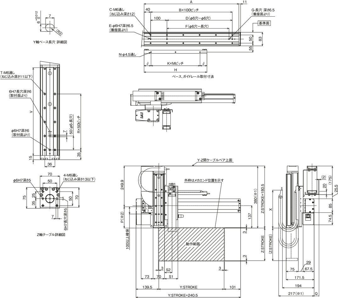
Dimension drawing
*1 The cable track may swell and turning slightly larger than the stated dimensions.
*2 A negative P dimension indicates that the motor unit end is located in front of the table end face.
(Note) The combination position on the figure is the home.
(Note) The figure is for the case where the configuration direction "1", the first wiring and the second wiring are both equipped with a cable track.
(Note) For details of the cable track and cable track moving end bracket, see page 4-537.
(Note) The Y-axis cable track guide rail must be fixed to the Y-axis mounting surface side. Be careful when installing because it protrudes outward from the Y-axis mounting surface.
Fix the moving end of the Z-axis cable track to the plate, etc., installed by the customer on the Z-axis table.

Dimension by stroke length
| Y: Stroke | 50 | 100 | 150 | 200 | 250 | 300 | 350 | 400 | 450 | 500 | 550 | 600 | 650 | 700 | 750 | 800 | 850 | 900 | 950 | 1000 | 1050 | 1100 |
|---|---|---|---|---|---|---|---|---|---|---|---|---|---|---|---|---|---|---|---|---|---|---|
| A | 230 | 280 | 330 | 380 | 430 | 480 | 530 | 580 | 630 | 680 | 730 | 780 | 830 | 880 | 930 | 980 | 1030 | 1080 | 1130 | 1180 | 1230 | 1280 |
| B | 1 | 2 | 2 | 3 | 3 | 4 | 4 | 5 | 5 | 6 | 6 | 7 | 7 | 8 | 8 | 9 | 9 | 10 | 10 | 11 | 11 | 12 |
| C | 4 | 6 | 6 | 8 | 8 | 10 | 10 | 12 | 12 | 14 | 14 | 16 | 16 | 18 | 18 | 20 | 20 | 22 | 22 | 24 | 24 | 26 |
| D | 0 | 100 | 100 | 200 | 200 | 300 | 300 | 400 | 400 | 500 | 500 | 600 | 600 | 700 | 700 | 800 | 800 | 900 | 900 | 1000 | 1000 | 1100 |
| E | 2 | 3 | 3 | 3 | 3 | 3 | 3 | 3 | 3 | 3 | 3 | 3 | 3 | 3 | 3 | 3 | 3 | 3 | 3 | 3 | 3 | 3 |
| F | 0 | 0 | 80 | 180 | 180 | 280 | 280 | 380 | 380 | 480 | 480 | 580 | 580 | 680 | 680 | 780 | 780 | 880 | 880 | 980 | 980 | 1080 |
| G | 0 | 0 | 1 | 1 | 1 | 1 | 1 | 1 | 1 | 1 | 1 | 1 | 1 | 1 | 1 | 1 | 1 | 1 | 1 | 1 | 1 | 1 |
| H | 210 | 235 | 260 | 285 | 310 | 335 | 360 | 385 | 410 | 435 | 460 | 485 | 510 | 535 | 560 | 585 | 610 | 635 | 660 | 685 | 710 | 735 |
| J | 30 | 42.5 | 30 | 42.5 | 30 | 42.5 | 30 | 42.5 | 30 | 42.5 | 30 | 42.5 | 30 | 42.5 | 55 | 30 | 42.5 | 55 | 30 | 42.5 | 55 | 17.5 |
| K | 1 | 1 | 1 | 1 | 2 | 2 | 2 | 2 | 2 | 2 | 2 | 2 | 3 | 3 | 3 | 3 | 3 | 3 | 3 | 3 | 3 | 4 |
| M | 150 | 150 | 200 | 200 | 125 | 125 | 150 | 150 | 175 | 175 | 200 | 200 | 150 | 150 | 150 | 175 | 175 | 175 | 200 | 200 | 200 | 175 |
| N | 2 | 2 | 2 | 2 | 3 | 3 | 3 | 3 | 3 | 3 | 3 | 3 | 4 | 4 | 4 | 4 | 4 | 4 | 4 | 4 | 4 | 5 |
Dimension by stroke length
| Size of cable track | CT | CTM | CTL | CTXL |
|---|---|---|---|---|
| Q | 18 | 30 | 45 | 63 |
| S1 | 82 | 94 | 107 | - |
| S2 | 46 | 52.5 | 59 | - |
(Note) The dimensions of Q, S1, and S2 vary depending on the size of the cable track.
Dimension by stroke length
| Z: Stroke | 50 | 75 | 100 | 125 | 150 | 175 | 200 | 250 | 300 |
|---|---|---|---|---|---|---|---|---|---|
| P(※2) | -19.4 | 5.6 | 30.6 | 55.6 | 80.6 | 105.6 | 130.6 | 180.6 | 230.6 |
| R | 1 | 2 | 2 | 3 | 3 | 4 | 4 | 5 | 6 |
| T | 4 | 6 | 6 | 8 | 8 | 10 | 10 | 12 | 14 |
| V | 164 | 189 | 214 | 239 | 264 | 289 | 314 | 364 | 414 |
| X | 188 | 232 | |||||||


