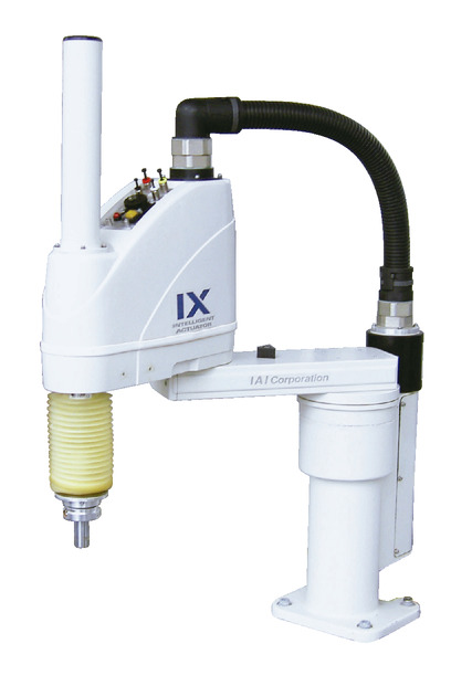
Model specification
| Model | Axis Configuration | Arm length (mm) | Motor capacity (W) | Operating range | Positioning repeatability (mm) (Note 1) | Max. PTP operation speed (Note 2) | Standard cycle time (s) (Note 3) | Load Capacity (kg) | Control range of 3rd axis (vertical axis) push force (N) | Allowable load of 4th axis | ||||
|---|---|---|---|---|---|---|---|---|---|---|---|---|---|---|
| Rated | Maximum | Upper limit (Note 4) | Lower limit (Note 4) | Allowable moment of inertia (kg・m2) (Note 5) | Allowable torque (N·m) | |||||||||
| IX-NNW6020H-①-T2-② 【IX-NNW6030H-①-T2-②】 | 1-Axis | 1st arm | 350 | 400 | ±120 degree | ±0.010 (XY) | 7232mm/s (combined speed) | 0.47 | 2 | 10 | 180.0 | 93.0 | 0.06 | 3.7 |
| 2-Axis | 2nd arm | 250 | 200 | ±145 degrees | ||||||||||
| 3-Axis | Vertical axis | - | 200 | 200mm 【300mm】 | ±0.010 | 1473mm/s | ||||||||
| 4-Axis | Rotating shaft | - | 100 | ±360 degrees | ±0.005 | 1857 degrees/s | ||||||||
Legend ① Cable length ② Option
Actuator specification
| Heading | Contents |
|---|---|
| Encoder type | Absolute |
| User wiring | 23-core AWG26 shielded waterproof connector |
| User piping | Air tube (O.D. ø6, I.D. ø4) x 2 (Normal working pressure 0.8 MPa) Air tube (O.D. ø4, I.D. ø2.5) x 2 (Normal working pressure 0.8 MPa) |
| Alarm indicator light (Note 6) | 1 small red LED indicator (24V DC supply required) |
| Brake release switch (Note 7) | Brake release switch for vertical axis fall prevention (24V DC supply required) |
| Ambient temperature/humidity | Temperature 0 - 40℃, humidity 20 - 85% RH or less (no condensation) |
| Body weight | 34.5kg |
| Cable length (Note 8) | 5L: 5m (standard) 10L: 10m |
| Protective structure (Note 9) | Equivalent to IP65 |
| Air purge pressure (Note 10) | 0.3MPa or more (maximum 0.6MPa or less) (clean dry air) |
Adaptive controller
The actuators introduced in this page are controllable using the controllers shown below. Please select their type based on intended usage.
| Name | Appearance | Max. connectable axis No. | Power source voltage | Control method | Maximum positioning points | ||||||||||||||
|---|---|---|---|---|---|---|---|---|---|---|---|---|---|---|---|---|---|---|---|
| Positioner | Pulse train | Program | Network *Select | ||||||||||||||||
| DV | CC | CIE | PR | CN | ML | ML3 | EC | EP | PRT | SSN | ECM | ||||||||
| XSEL-PX/QX | 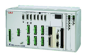 | 6 | Three-phase AC200V | - | - | ● | ● | ● | - | ● | - | - | - | - | ● | - | - | - | 20000 |
| XSEL-RAX/SAX XSEL-RAXD/SAXD (for IX) | 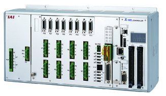 | 8 | - | - | ● | ● | ● | - | ● | - | - | - | ● | ● | - | - | - | 36666 (depending on type) | |
(Note) Refer to page 7-17 for network abbreviation symbols such as DV and CC.
(Note) It can control up to SCARA + 4-axis robot.
(Note) Select XSEL-RAXD / SAXD when connecting two SCARA robots. However, the SCARA robots may not be able to be connected depending on the combination. Refer to page 7-289.
Oversea specification
(Note) CE is optional.
Important notes on selection
| (1) Please refer to page 6-559 for (Note 1) to (Note 11). (2) SCARA robots cannot operate continuously at 100% speed and acceleration. Refer to the technical information on page 1-507 for operating conditions. (3) Figures in 【 】 are for the models with a vertical axis of 300 mm. Other specifications and dimensions are common for both vertical axis of 200mm and 300mm. (4) An adjustment jig is required to perform absolute reset which is needed whenever the encoder absolute data was lost. Refer to page 6-575 for further details. (5) Flange option is available. Refer to page 6-680 for further details. |
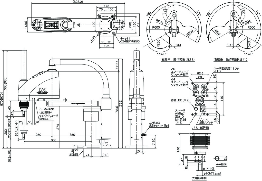
Dimension drawing
ST: Stroke
*1 The external force applied to the spacer should be 30N or less in the axial direction and 2N・m or less in the rotational direction. (For each spacer)
*2 The LED operates under a condition where the LED terminal is wired in the user's wiring so that it receives 24V of DC while receiving signals from the I/O output of the controller.
*3 3-M4 depth 8 penetrates the side of the arm. Please note that long mounting screws will interfere with internal mechanical components.
Please be sure to use sealing tape etc. to seal the screws.
(Note) Cable/Piping
・Motor ・Encoder cable 5m/10m
・Brake power supply cable 5m/10m
・User wiring cable 5m/10m
・Air piping (4 pieces) 0.15m
