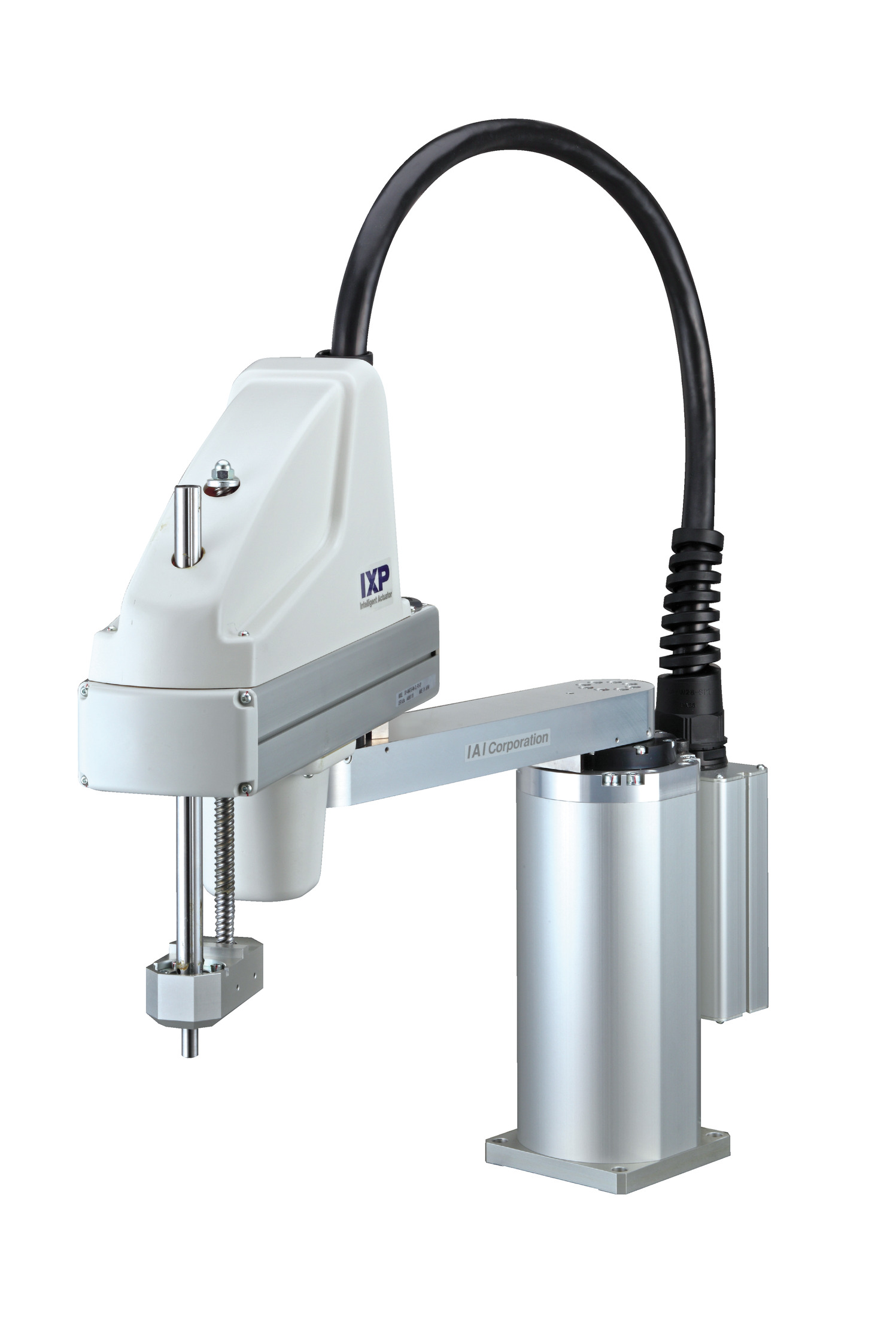
(Note) The photograph shows the 4-axis specification.
Main specification
| Heading | Contents | |||||
|---|---|---|---|---|---|---|
| 3-axis type | 4-axis type | 3-axis specification with medium gripper (GM) | 3-axis specification with large gripper (GL) | |||
| Maximum load capacity (kg) (Note1) | 3 | 0.5 | 1.5 | |||
| Speed (Note2) | Maximum resultant speed (mm/s) | 2726 | 1908 | |||
| Maximum speed of each axis | 1st arm (degree/s) | 240 | 168 | |||
| 2nd arm (degree/s) | 380 | 266 | ||||
| Vertical axis (mm/s) | 270 | 189 | ||||
| Rotating axis (degree/s) | - | 1000 | - | - | ||
| Gripper (mm/s) | - | - | 94 (one finger) | 125 (one finger) | ||
| Push force (N) | Upper limit | Unavailable | ||||
| Minimum | Unavailable | |||||
| Arm length (mm) | 350 | |||||
| Arm length of each axis (mm) | 1st arm | 160 | ||||
| 2nd arm | 190 | |||||
| Operating range of each axis | 1st arm (degree) | ±127 | ||||
| 2nd arm (degree) | ±127 | |||||
| Vertical axis (mm) | 150 | 100 | ||||
| Rotating axis (degree) | - | ±360 | - | - | ||
| Gripper (mm) | - | - | 14 (both fingers) | 22 (both fingers) | ||
| Heading | Contents | ||||
|---|---|---|---|---|---|
| 3-axis type | 4-axis type | 3-axis specification with medium gripper (GM) | 3-axis specification with large gripper (GL) | ||
| Repeated positioning accuracy (Note3) | Horizontal plane | ±0.030 mm | |||
| Vertical axis | ±0.020 mm | ||||
| Rotating shaft | - | ±0.020 degree | - | - | |
| Gripper | - | - | ±0.010 mm | ±0.010 mm | |
| User wiring | 6-core AWG24 (Rated 30V/Max. 2A) 5 pairs AWG26 (Rated 30V/Max. 1A) | User wiring is not supported because the gripper wiring is used. | |||
| User piping | Air tube (O.D. ø4, I.D. ø2.5) x 3 (Maximum working pressure 0.8 MPa) | ||||
| Alarm indicator light | Absent | ||||
| Brake release switch | Absent | ||||
| Tip shaft | Allowable torque | 1.4 N・m | |||
| Allowable load moment | 2.9 N・m | Ma1.9,Mb2.7,Mc2.9 N・m | Ma2.9,Mb2.9,Mc2.9 N・m | ||
| Ambient operating temperature and humidity | Temperature 0-40℃ Humidity 20-85% RH or less (no condensation) | ||||
| Protection grade | IP20 | ||||
| Vibration resistant/Shock resistant | No shock or vibration | ||||
| Noise (Note 4) | 75dB or less | ||||
| Compatible to overseas standards | CE mark, RoHS compliant | ||||
| Motor type | Pulse motor | ||||
| Motor capacity | 1st arm | - | |||
| 2nd arm | - | ||||
| Vertical axis | - | ||||
| Rotating shaft | - | - | - | - | |
| Encoder type | Battery-less absolute | ||||
| Encoder pulse number | 8192 pulse/rev | ||||
| Delivery | Written in [Reference for delivery] section of the homepage | ||||
(Note) The gripper encoder is of an incremental specification with 800 pulse/rev.
Types of installed gripper
| IXP-3N3515GM | Medium gripper RCP4-GRSML installed at the tip of vertical axis |
| IXP-3N3510GL | Large gripper RCP4-GRSLL installed at the tip of vertical axis |
Adaptive controller
The actuators introduced in this page are controllable using the controllers shown below. Please select their type based on intended usage.
| Name | Appearance | Max. connectable axis No. | Power source voltage | Control method | Maximum positioning points | ||||||||||||||
|---|---|---|---|---|---|---|---|---|---|---|---|---|---|---|---|---|---|---|---|
| Positioner | Pulse train | Program | Network ※Select | ||||||||||||||||
| DV | CC | CIE | PR | CN | ML | ML3 | EC | EP | PRT | SSN | ECM | ||||||||
| MSEL-PCX/PGX | 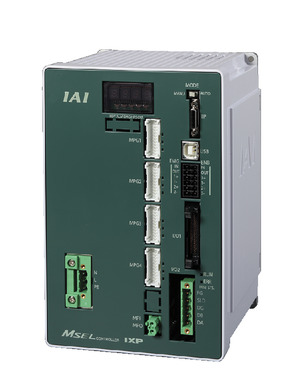 | 4 | Single phase AC 100 - 230V | - | - | ● | ● | ● | - | ● | - | - | - | ● | ● | ● | - | - | 30000 |
(Note) Refer to page 7-17 for network abbreviation symbols such as DV and CC.
Oversea specification
Important notes on selection
| (1) Refer to page 4-747 for (Note 1) to (Note 5). (2) Vertical axis has no brake installed. (3) Vertical axis does not support push control. (4) If a tool is installed or a spring or other buffer is provided for push-motion, the allowable push force is 60 N or less. (5) The arm will once extend in a straight line when switching the arm thread. Please be careful of interference with peripheral devices. (6) Flange option is available. Refer to page 4-742 for further details. |
Dimension drawing
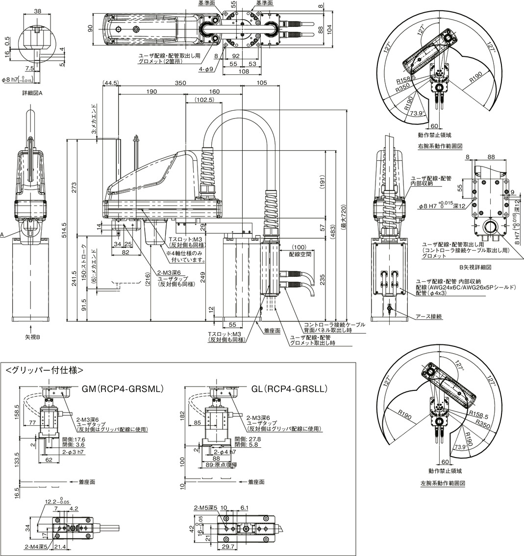
(Note) The controller connecting cable will be 3 units instead when the 3-axis specification is selected.
(Note) The vertical axis stroke for gripper installed specifications are 150 mm for GM (RCP4-GRSML) and 100 mm for GL (RCP4-GRSLL).
(Note) The overhang limit for gripper installed specification is 0 mm horizontally and 50 mm vertically. (Refer to the page 4-747 (Note 5))
Mass
| Heading | Contents | |
|---|---|---|
| Mass | 3-axis type | 12.0kg |
| 4-axis type | 13.0kg | |
| 3-axis specification with medium gripper (GM) | 12.5kg | |
| 3-axis specification with large gripper (GL) | 13.0kg | |
Cycle time
| Heading | Time | |
|---|---|---|
| Standard cycle time Continuous cycle time | 3-axis type | 0.69 sec |
| 4-axis type | 0.69 sec | |
| 3-axis specification with medium gripper (GM) | 0.69 sec | |
| 3-axis specification with large gripper (GL) | 1.08 sec | |
The standard / continuous cycle time indicates the time required when operating with the fastest round-trip operation setting under the following conditions.
Transfer mass of 1kg, vertical movement of 25mm and horizontal movement of 300mm (coarse positioning arch motion)
The weight of the gripper is also included in the transport mass for the gripper installed specification.
The opening and closing time of the gripper is not included in the cycle time.
[Standard cycle time]
The time required for the fastest operation. Generally, this is a guide for high-speed performance.
[Continuous cycle time]
The cycle time for continuous operation.

Allowable load moment of inertia at the tip shaft
| Number of axes | Allowable load moment of inertia at the tip shaft |
|---|---|
| 3-axis type | 0.01 kg・m2 |
| 4-axis type | 0.003 kg・m2 |
| 3-axis specification with medium gripper (GM) | 0.002 kg・m2 |
| 3-axis specification with large gripper (GL) | 0.009 kg・m2 |
The allowable load moment of inertia of the tip axis is the allowable moment of inertia when the tip spline axis of the SCARA robot is converted to the center. The offset amount from the tip axis to the load center should be within the following values. If the position of the center of gravity of the load deviates from the tip axis, it is required to reduce the speed and acceleration as appropriate.
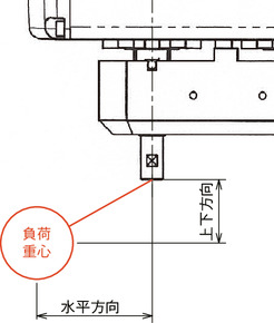
| Horizontal direction | Vertical direction | |
|---|---|---|
| Without gripper | 30mm or less | 100mm or less |
| With gripper | 0mm | 50mm or less |
The vertical direction of the specifications with gripper is from the finger mounting surface of the gripper to the load center of gravity.
Guideline for acceleration / deceleration setting
If continuous operation is required, operate within the range of the graph for acceleration / deceleration setting and duty cycle setting guideline.
PTP operation
For speed and acceleration / deceleration, the operable value when the transport load is taken into consideration is set as 100% (optimal speed / optimum acceleration / deceleration feature). Adjust to the desired speed and acceleration / deceleration.
(1) Optimal speed / optimum acceleration / deceleration feature does not provide guarantee for it to operate in all operation patterns.
(2) Slow down the speed or acceleration / deceleration as appropriate if significant vibration occurs, for it may cause a malfunction or may shorten its service life.
CP operation
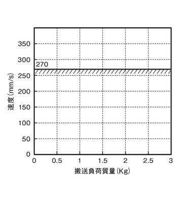
Set the speed and acceleration / deceleration up to the values in the graph below.
(1) Slow down the speed or acceleration / deceleration as appropriate if significant vibration occurs, for it may cause a malfunction or may shorten its service life.
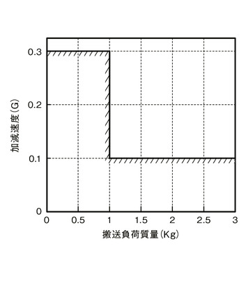
Duty cycle setting
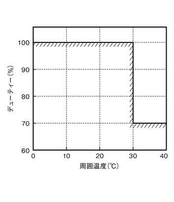
The duty cycle is the operating rate in percentage (%) of the time the robot is operating during one cycle. This robot has a duty cycle limit based on ambient temperature to suppress the heat generation of the motor unit and reducing gear. Operate both PTP and CP operation within the values in the graph below. Do not run a continuous operation for more than 30 minutes.
(1) Operate with duty cycle within the upper limit for this may shorten the service life of the motor unit and the reducing gear.


