
Product feature


Attachment orientation
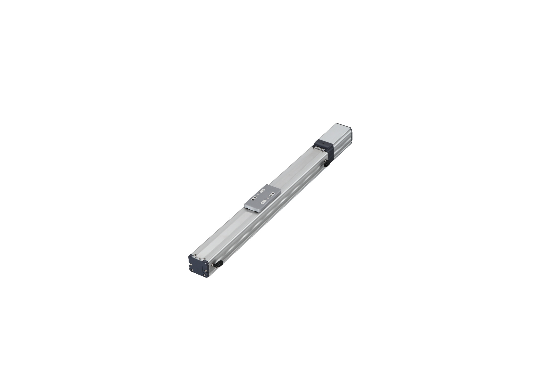
Actuator specification
| Model | Lead (mm) | Connecting controller | Maximum Load Capacity | Stroke (mm) | |
|---|---|---|---|---|---|
| Horizontal (kg) | Vertical (kg) | ||||
| RCP5CR-SA6C-WA-42P-20-①-②-③-④ | 20 | High Output Enabled | 10 | 1 | 50 - 800 (Every 50mm) |
| High Output Disabled | 6 | 0.5 | |||
| RCP5CR-SA6C-WA-42P-12-①-②-③-④ | 12 | High Output Enabled | 15 | 2.5 | |
| High Output Disabled | 8.5 | 2 | |||
| RCP5CR-SA6C-WA-42P-6-①-②-③-④ | 6 | High Output Enabled | 25 | 6 | |
| High Output Disabled | 16 | 5 | |||
| RCP5CR-SA6C-WA-42P-3-①-②-③-④ | 3 | High Output Enabled | 25 | 16 | |
| High Output Disabled | 19 | 10 | |||
Code description ① Stroke ② Applicable controller ③ Cable length ④ Options
| Lead (mm) | Connecting controller | 50 - 400 (Every 50mm) | 450 (mm) | 500 (mm) | 550 (mm) | 600 (mm) | 650 (mm) | 700 (mm) | 750 (mm) | 800 (mm) | Suction amount (Nℓ/min) |
|---|---|---|---|---|---|---|---|---|---|---|---|
| 20 | High Output Enabled | 1440 <1280> | 1335 <1280> | 1130 | 970 | 840 | 735 | 650 | 575 | 100 | |
| High Output Disabled | 960 | 840 | 735 | 650 | 575 | ||||||
| 12 | High Output Enabled | 900 | 885 | 735 | 620 | 535 | 460 | 405 | 355 | 315 | 70 |
| High Output Disabled | 600 | 535 | 460 | 405 | 355 | 315 | |||||
| 6 | High Output Enabled | 450 | 435 | 365 | 305 | 265 | 230 | 200 | 175 | 155 | 30 |
| High Output Disabled | 300 | 265 | 230 | 200 | 175 | 155 | |||||
| 3 | High Output Enabled | 225 | 215 | 180 | 150 | 130 | 115 | 100 | 85 | 75 | 15 |
| High Output Disabled | 150 | 130 | 115 | 100 | 85 | 75 | |||||
(Measured in mm/s)
(Note) < > is applicable when operated vertically.
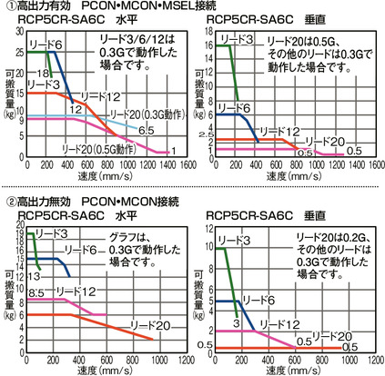
Correlation diagram of speed and load capacity
Actuator specification
| Heading | Contents |
|---|---|
| Drive system | Ball screw φ10mm, rolled C10 |
| Positioning repeatability (Note 1) | ±0.02mm [±0.03] |
| Lost motion | 0.1mm or less |
| Base | Material: White alumite treated aluminum |
| Allowable static moment value | Ma direction 38.3N・m Mb direction 54.7N・m Mc direction 81.0N・m |
| Allowable dynamic moment (Note2) | Ma direction 11.6N・m Mb direction 16.6N・m Mc direction 24.6N・m |
| Cleanliness | Class 10 (Fed.Std.209D), equivalent to class 2.5 (ISO 14644-1 standard) |
| Ambient operating temperature and humidity | 0 - 40℃, 85%RH or less (no condensation) |
(Note 1) [ ] is for lead 20.
(Note 2) Based on standard rated life of 5,000km. Life time travelling distance differs based on operating condition and attached condition.
Refer page 1-180 for the operating life.
Adaptive controller
The actuators introduced in this page are controllable using the controllers shown below. Please select their type based on intended usage.
| Name | Appearance | Max. connectable axis No. | Power source voltage | Control method | Maximum positioning points | ||||||||||||||
|---|---|---|---|---|---|---|---|---|---|---|---|---|---|---|---|---|---|---|---|
| Positioner | Pulse train | Program | Network *Select | ||||||||||||||||
| DV | CC | CIE | PR | CN | ML | ML3 | EC | EP | PRT | SSN | ECM | ||||||||
| MCON-C/CG | 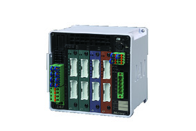 | 8 | DC24V | - | - | - | ● | ● | ● | ● | ● | - | ● | ● | ● | ● | ● | ● | 256 |
| MCON-LC/LCG | 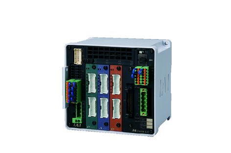 | 6 | - | - | ● | ● | ● | - | ● | ● | - | - | ● | ● | ● | - | - | 256 | |
| MSEL-PC/PG | 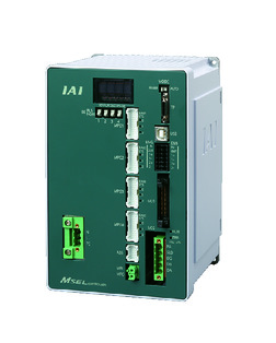 | 4 | Single phase AC 100 - 230V | - | - | ● | ● | ● | - | ● | - | - | - | ● | ● | ● | - | - | 30000 |
| PCON-CB/CGB | 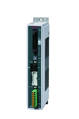 | 1 | DC24V | ● *Selectable | ● *Selectable | - | ● | ● | ● | ● | ● | ● | ● | ● | ● | ● | - | - | 512 (768 for network specification) |
| PCON-CYB/PLB/POB |  | 1 | ● *Selectable | ● *Selectable | - | - | - | - | - | - | - | - | - | - | - | - | - | 64 | |
| RCON |  | 16 | - | - | - | ● | ● | ● | ● | - | - | - | ● | ● | ● | - | - | 128 | |
(Note) Refer to page 7-17 for network abbreviation symbols such as DV and CC.
(Note) High-power setting is only available in MCON with an option for "high-power setting specification". The maximum number of connectable axes when high output is enabled is C: 4, LC: 3.
Oversea specification


Important notes on selection
| (1) Load capacity shown in "Actuator specification" refers to its maximum value, for the actual value changes based on its acceleration. Please refer to "RCP5 / Payload capacity table by speed and acceleration" on page 1-441 and 1-442 of the General Catalogue 2017 for further details. (2) Please refer to page 1-387 of general catalogue 2017 for pressing motion. (3) Precaution is required depending on attachment orientation. Refer page 1-199 for further details. (4) The approximate overhang load length is 150mm or less in Ma, Mb and Mc directions. (5) Please refer to the diagram on page 1-16 for the allowable moment direction and overhang load length. |
Dimension drawing
M.E.: Mechanical end
S.E.: Stroke end
(Note) Ensure the slider does not collide with other items, for it will return to M.E. after homing process.
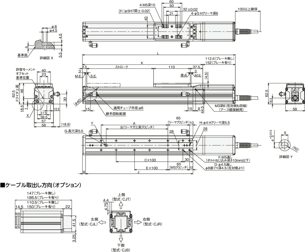
Dimension/Mass by stroke
| Stroke | 50 | 100 | 150 | 200 | 250 | 300 | 350 | 400 | 450 | 500 | 550 | 600 | 650 | 700 | 750 | 800 | |
|---|---|---|---|---|---|---|---|---|---|---|---|---|---|---|---|---|---|
| L | Without brake | 323 | 373 | 423 | 473 | 523 | 573 | 623 | 673 | 723 | 773 | 823 | 873 | 923 | 973 | 1023 | 1073 |
| With brake | 362.5 | 412.5 | 462.5 | 512.5 | 562.5 | 612.5 | 662.5 | 712.5 | 762.5 | 812.5 | 862.5 | 912.5 | 962.5 | 1012.5 | 1062.5 | 1112.5 | |
| A | 0 | 100 | 100 | 200 | 200 | 300 | 300 | 400 | 400 | 500 | 500 | 600 | 600 | 700 | 700 | 800 | |
| B | 0 | 85 | 85 | 185 | 185 | 285 | 285 | 385 | 385 | 485 | 485 | 585 | 585 | 685 | 685 | 785 | |
| C | 1 | 1 | 2 | 2 | 3 | 3 | 4 | 4 | 5 | 5 | 6 | 6 | 7 | 7 | 8 | 8 | |
| D | 4 | 4 | 6 | 6 | 8 | 8 | 10 | 10 | 12 | 12 | 14 | 14 | 16 | 16 | 18 | 18 | |
| E | 0 | 0 | 0 | 1 | 1 | 2 | 2 | 3 | 3 | 4 | 4 | 5 | 5 | 6 | 6 | 7 | |
| F | 4 | 6 | 6 | 8 | 8 | 10 | 10 | 12 | 12 | 14 | 14 | 16 | 16 | 18 | 18 | 20 | |
| G | 0 | 1 | 1 | 1 | 1 | 1 | 1 | 1 | 1 | 1 | 1 | 1 | 1 | 1 | 1 | 1 | |
| H | 2 | 3 | 3 | 3 | 3 | 3 | 3 | 3 | 3 | 3 | 3 | 3 | 3 | 3 | 3 | 3 | |
| J | 172 | 222 | 272 | 322 | 372 | 422 | 472 | 522 | 572 | 622 | 672 | 722 | 772 | 822 | 872 | 922 | |
| K | 210.5 | 260.5 | 310.5 | 360.5 | 410.5 | 460.5 | 510.5 | 560.5 | 610.5 | 660.5 | 710.5 | 760.5 | 810.5 | 860.5 | 910.5 | 960.5 | |
| Mass (kg) | Without brake | 1.7 | 1.8 | 2.0 | 2.2 | 2.4 | 2.5 | 2.7 | 2.9 | 3.1 | 3.2 | 3.4 | 3.6 | 3.8 | 3.9 | 4.1 | 4.3 |
| With brake | 1.9 | 2.0 | 2.2 | 2.4 | 2.6 | 2.7 | 2.9 | 3.1 | 3.3 | 3.4 | 3.6 | 3.8 | 4.0 | 4.1 | 4.3 | 4.5 | |