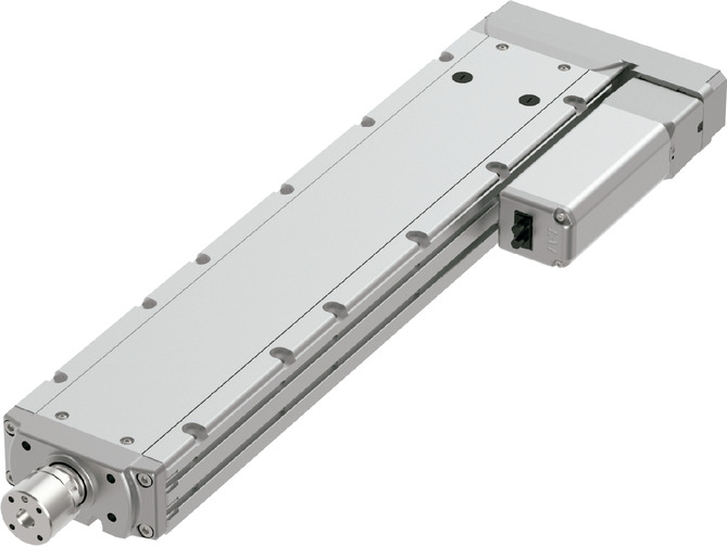
(Note) Photo above shows the motor reversing specification (Motor reversing on the left)(ML).
Main specification
| Heading | Contents | |||||
|---|---|---|---|---|---|---|
| Lead | Ball screw lead (mm) | 20 | 12 | 6 | 3 | |
| Horizontal | Load capacity (Note2) | Maximum load capacity (kg) | 12 | 25 | 40 | 60 |
| Speed/ Acceleration/Deceleration | Maximum speed (mm/s) | 1000 | 720 | 360 | 180 | |
| Rated acceleration/deceleration (G) | 0.3 | 0.5 | 0.5 | 0.3 | ||
| Maximum acceleration/deceleration (G) | 1 | 1 | 1 | 0.7 | ||
| Vertical | Load capacity | Maximum load capacity (kg) | 2 | 6 | 15 | 20 |
| Speed/ Acceleration/Deceleration | Maximum speed (mm/s) | 1000 | 720 | 360 | 180 | |
| Rated acceleration/deceleration (G) | 0.5 | 0.7 | 0.5 | 0.7 | ||
| Maximum acceleration/deceleration (G) | 1 | 1 | 1 | 0.7 | ||
| Thrust | Rated thrust (N) | 85 | 142 | 283 | 566 | |
| Brake | Brake specification | Non-excitation electromagnetic brake | ||||
| Brake retention force (kgf) | 2 | 6 | 15 | 20 | ||
| Stroke | Minimum stroke (mm) | 50 | 50 | 50 | 50 | |
| Maximum stroke (mm) | 500 | 500 | 500 | 500 | ||
| Stroke pitch (mm) | 50 | 50 | 50 | 50 | ||
(Note2) Assuming radial load supported by an external guide.
| Heading | Contents |
|---|---|
| Drive system | Ball screw φ10mm, rolled C10 |
| Accuracy of Repeating Positioning. | ±0.01mm |
| Lost motion | 0.1mm and below |
| Linear guide | Infinite linear circulation type |
| Rod | φ30mm Material: Stainless steel |
| Non-rotational accuracy of rod | 0° |
| Ambient operating temperature and humidity | 0 - 40℃, Max 85% RH and below (No condensation shall occur) |
| Protection grade | IP30 |
| Vibration resistant/Shock resistant | 4.9m/s2 100Hz and below |
| Compatible to overseas standards | CE mark, RoHS compliant |
| Motor type | AC servo motor |
| Encoder type | Battery-less absolute |
| Encoder pulse No. | 16384 pulse/rev |
| Delivery | Written in [Reference for delivery] section of the homepage |
Load capacity by speed and acceleration table
The base unit for load capacity is kilogram (kg). Empty column refers to inoperable motion.
| Orientation | Horizontal | Vertical | ||||||
|---|---|---|---|---|---|---|---|---|
| Lead (mm) | Acceleration (G) | |||||||
| 0.3 | 0.5 | 0.7 | 1.0 | 0.3 | 0.5 | 0.7 | 1.0 | |
| 20 | 12 | 10 | 8 | 6 | 2 | 2 | 1.5 | 1.5 |
| 12 | 25 | 25 | 20 | 15 | 6 | 6 | 6 | 5 |
| 6 | 40 | 40 | 30 | 25 | 15 | 15 | 12 | 12 |
| 3 | 60 | 50 | 40 | 20 | 20 | 20 | ||
Stroke and maximum speed
(Measured in mm/s)
| Stroke lead | 50 - 500 (50mm intervals) |
|---|---|
| 20 | 1000 |
| 12 | 720 |
| 6 | 360 |
| 3 | 180 |
Flexible volume (reference value)
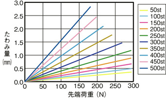
Allowable load mass at the rod tip
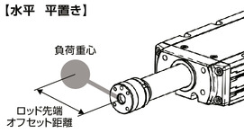
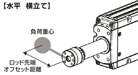
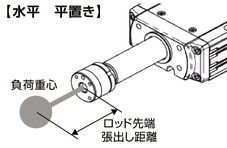
Horizontal
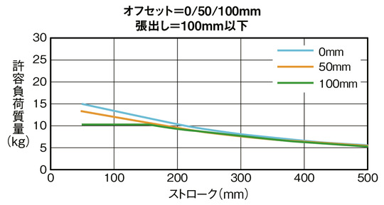
Condition required upon calculating allowable load mass
Load mass which assures a guide for 5000km lifetime traveling distance considering the moments resulting from acceleration and deceleration.
(Acceleration of 1.0G, and speed of 500mm/s)
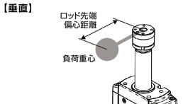
Vertical
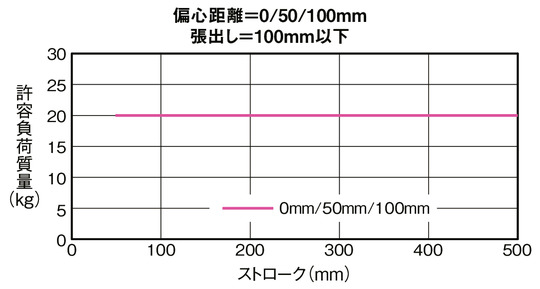
Condition required upon calculating allowable load mass
Load mass which assures a guide for 5000km lifetime traveling distance considering the moments resulting from acceleration and deceleration.
(Acceleration of 0.5G, and speed of 500mm/s)
Adaptive controller
The actuators introduced in this page are controllable using the controllers shown below. Please select their type based on intended usage.
| Name | Appearance | Max. connectable axis No. | Power source voltage | Control method | Maximum positioning points | |||||||||||||
|---|---|---|---|---|---|---|---|---|---|---|---|---|---|---|---|---|---|---|
| Positioner | Pulse train | Program | Network ※Select | |||||||||||||||
| DV | CC | PR | CN | ML | ML3 | EC | EP | PRT | SSN | ECM | ||||||||
| MSCON-C | 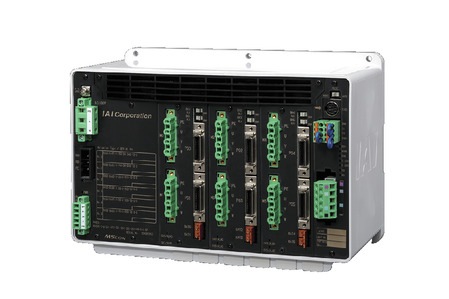 | 6 | Single phase AC 100V/200V | - | - | - | ● | ● | ● | ● | - | - | ● | ● | - | - | - | 256 |
| SCON-CAL/CGAL | 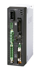 | 1 | ● | - | - | ● | ● | ● | ● | ● | - | ● | ● | ● | - | - | 512 (768 for network specification) | |
| SCON-CB/CGB | 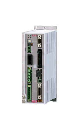 | 1 | ● | ● | - | ● | ● | ● | ● | ● | ● | ● | ● | ● | - | - | 512 (768 for network specification) | |
| SCON-LC/LCG | 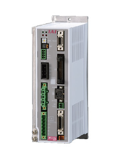 | 1 | - | - | ● | ● | ● | ● | ● | ● | - | ● | ● | ● | - | - | 512 (768 for network specification) | |
| SSEL-CS | 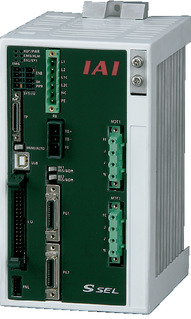 | 2 | ● | - | ● | ● | ● | ● | - | - | - | - | ● | - | - | - | 20000 | |
| XSEL-P/Q | 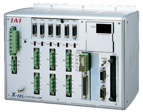 | 6 | Single phase AC200V Three-phase AC200V | - | - | ● | ● | ● | ● | - | - | - | - | ● | - | - | - | 20000 |
| XSEL-RA/SA | 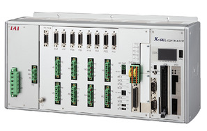 | 8 | - | - | ● | ● | ● | ● | - | - | - | ● | ● | - | - | - | 55000 (Vary based on type) | |
(Note) Please refer to page 6 -13 for abbreviated names of network (e.g. DV, CC).
Oversea specification
Important notes on selection
| (1) Load capacity drops when its speed increase. Please refer to "Load capacity by speed table" for further details. (2) Available duty depends on the operating condition (e.g.load mass, acceleration/deceleration). Please refer to page 1-449 for further information. (3) Radial cylinder comes with a built-in guide. Refer to "Allowable load mass at the rod tip" for the load mass allowable. (4) Safety measures may be required based on mounting orientation. Please refer to page 1-379 for further information. |
Dimension drawing
ST: Stroke
M.E.: Mechanical end
S.E.: Stroke end
(Note) The rod moves to the M.E. upon returning to origin, so please take precaution that it may not interfere with anything while the returning process is running.
(Note) Flange reamer bore positioned on the end has a deviation of ±1゜from the center of the rod. Attach the transferring load without using the reamer bore if the load's offset distance is too long, or a strict angle adjustment was required.
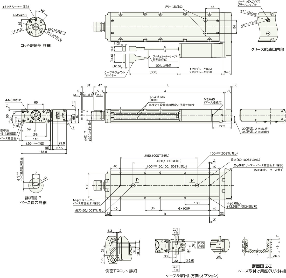
Dimension by stroke length
| Stroke | 50 | 100 | 150 | 200 | 250 | 300 | 350 | 400 | 450 | 500 | ||
|---|---|---|---|---|---|---|---|---|---|---|---|---|
| L | 263 | 313 | 363 | 413 | 463 | 513 | 563 | 613 | 663 | 713 | ||
| A | 236 | 286 | 336 | 386 | 436 | 486 | 536 | 586 | 636 | 686 | ||
| B | 192 | 242 | 292 | 342 | 392 | 442 | 492 | 542 | 592 | 642 | ||
| F | 112 | 62 | 112 | 62 | 112 | 62 | 112 | 62 | 112 | 62 | ||
| G | 0 | 1 | 1 | 1 | 1 | 2 | 2 | 3 | 3 | 4 | ||
| H | 4 | 6 | 6 | 8 | 8 | 10 | 10 | 12 | 12 | 14 | ||
| J | - | - | 162 | 212 | 262 | 312 | 362 | 412 | 462 | 512 | ||
| M | 1 | 1 | 1 | 2 | 2 | 2 | 2 | 2 | 2 | 2 | ||
| Allowable static load at the rod tip (N) | 294 | 294 | 294 | 294 | 294 | 269 | 241 | 218 | 198 | 181 | ||
| Allowable static torque at the rod tip (Nm) | 20 | 20 | 20 | 20 | 20 | 20 | 20 | 20 | 20 | 20 | ||
| Life span of 3000km | Allowable dynamic load on the rod tip (N) | Off-set 0mm | 147 | 147 | 137 | 121 | 107 | 96 | 87 | 79 | 72 | 65 |
| Off-set 100mm | 100 | 100 | 100 | 100 | 99 | 90 | 82 | 75 | 68 | 63 | ||
| Allowable dynamic torque at the rod tip (N・m) | 10.0 | 10.0 | 10.0 | 10.0 | 9.9 | 9.0 | 8.2 | 7.5 | 6.8 | 6.3 | ||
| Life span of 5000km | Allowable dynamic load on the rod tip (N) | Off-set 0mm | 147 | 133 | 115 | 101 | 90 | 80 | 72 | 65 | 59 | 54 |
| Off-set 100mm | 100 | 100 | 100 | 92 | 83 | 75 | 68 | 62 | 56 | 51 | ||
| Allowable dynamic torque at the rod tip (N・m) | 10.0 | 10.0 | 10.0 | 9.2 | 8.3 | 7.5 | 6.8 | 6.2 | 5.6 | 5.1 | ||
Mass by stroke length
| Stroke | 50 | 100 | 150 | 200 | 250 | 300 | 350 | 400 | 450 | 500 | |
|---|---|---|---|---|---|---|---|---|---|---|---|
| Mass (kg) | Brake present | 5.2 | 5.9 | 6.5 | 7.2 | 7.8 | 8.5 | 9.1 | 9.8 | 10.4 | 11.1 |
| Brake absent | 5.5 | 6.2 | 6.8 | 7.5 | 8.1 | 8.8 | 9.4 | 10.1 | 10.7 | 11.4 | |


